Super Kaos from Lazerworks Short Kit.
 05-29-2019, 09:41 AM
#51

Mike, when I cut it with denatured alcohol it becomes very thin and will really wick into the wood which is perfect for you. Besides the fuel proofing it will strengthen the wood as an added bonus!
Here's the ratio that I use, as an example:
5 cc of resin + 5 cc of hardener then quick mix followed by adding 10cc of alcohol.
Here's the ratio that I use, as an example:
5 cc of resin + 5 cc of hardener then quick mix followed by adding 10cc of alcohol.
 05-29-2019, 10:36 AM
#53
05-29-2019, 03:32 PM
#54
Thread Starter

I actually have a fresh package of Z-Poxy sitting on the shelf. I'm just frustrated over the loss of Kwik Poly because it really was the "Stuff of a Thousand Uses". A shame as the owner was pleasant to work with. I got the impression that it was a one man operation or at least a pretty small business.
 05-29-2019, 07:03 PM
#55
Thread Starter
Yes, the sleeves will be anchored at both ends and in the middle. I know that everyone has their personal favorites when it come to control linkages but I've personally had good results with Golden Rods. It may just be that their stability exceeds my ability to tell the difference.
05-29-2019, 07:20 PM
#56
Thread Starter
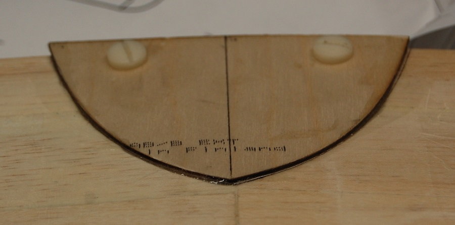
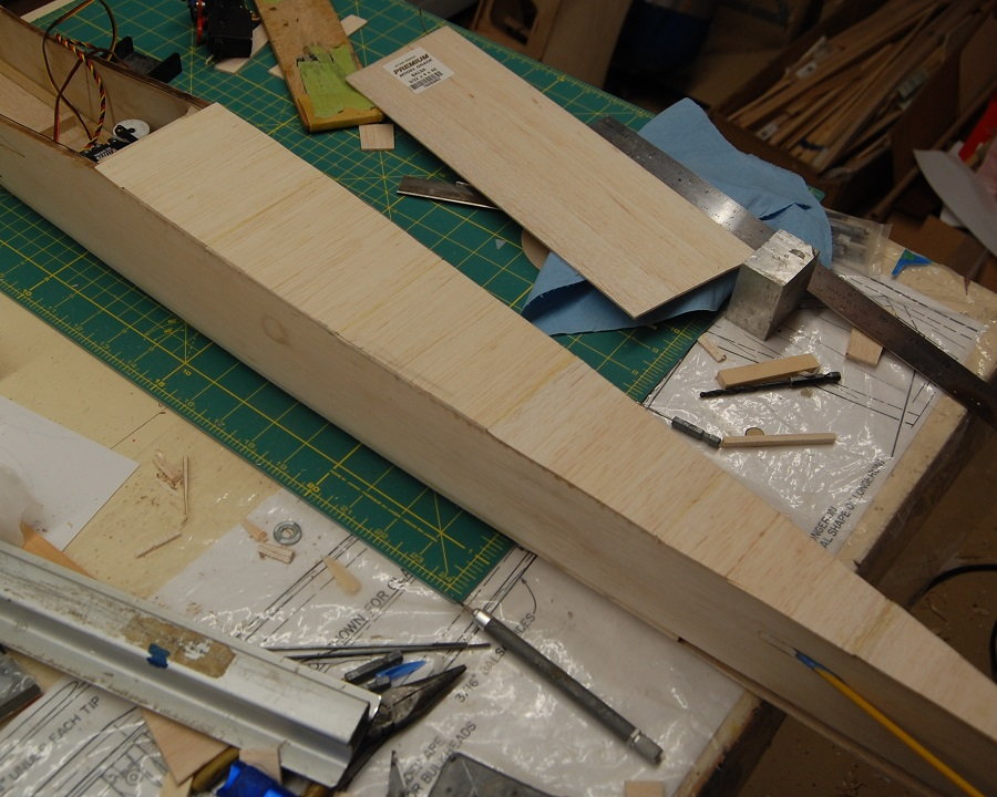
The rear wing mount. Per the plans there should be 6-32 blind nuts for the wing hold down screws. I'm not a fan of doing it that way. if one were using a single aileron servo driving torque rods it makes sense to get as much clearance for the torque rod arms as possible. As a result you could use small fasteners as far back as possible. Since I am putting servos out in the wing this isn't an issue for me. I'm going to pass on the blind nuts and go with the usual 1/4 - 20 nylon wing bolts going into a tapped plywood plate. If I had been paying more attention to the design I would have followed the way it is done on the Ultimate Kaos in which the bolts pass through the wing just ahead of the trailing edge stock. As it is I think with the fiberglass reinforcement of the center section and the 1/16 plywood wing plate the mounting will be plenty strong, the Ultimate Kaos method is just better. In looking at the photo the plate looks a little skewed but that is due to camera angle. it actually sits level.
05-29-2019, 07:27 PM
#57
Thread Starter
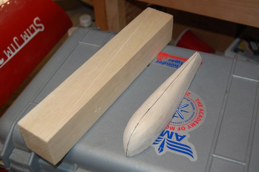
One of the wing tips and the block that the other wing tip is going to be carved from. I roughed out the tip shape on the bandsaw and then whittled and sanded to the final shape.
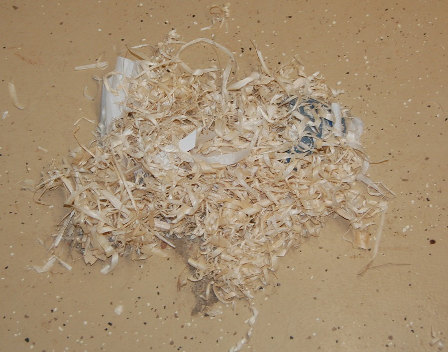
A small sample of what a lot of the block was turned into. These are the bits that didn't look like a wing tip.
A small sample of what a lot of the block was turned into. These are the bits that didn't look like a wing tip.
05-30-2019, 10:53 AM
#58
Nice progress Matt. I'm with you, no metal hardware for one-piece wing anchoring. I tap basswood plank for the 1/4-20 nylon bolts as it seems to hold threads better than ply. All my pattern ships get balsa wing tips too, even if not originally kitted that way. I look forward to seeing your continued progress.
Lonnie
Lonnie
Last edited by Glowgeek; 05-30-2019 at 11:02 AM.
05-30-2019, 11:17 AM
#59
Matt, looks like the wings are set up to use film covering, are you planning to film cover the entire plane? If so, some pics of how you cover the compound curve of the nose would be great. Admittedly I'm not the best at covering that area and mostly opt to sheet, glass and paint as a result.
05-31-2019, 07:41 AM
#60
Thread Starter
Matt, looks like the wings are set up to use film covering, are you planning to film cover the entire plane? If so, some pics of how you cover the compound curve of the nose would be great. Admittedly I'm not the best at covering that area and mostly opt to sheet, glass and paint as a result.
05-31-2019, 07:50 AM
#61
Thread Starter
Buttoning up the tail of the airplane. It's just done with 3/32 sheet. I used titebond glue since it sands more smoothly than CA. It won't be as rounded over as the top deck but the lower corners will still be blended a little to smooth things up.
05-31-2019, 08:29 AM
#62
Thread Starter
Here is the basic wing structure done. No tips yet and as can be seen a couple of the ribs don't have their cap strips. The cap strips will be finished when the aileron servo mounts are added. The center section hasn't been glassed yet.
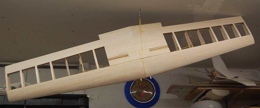
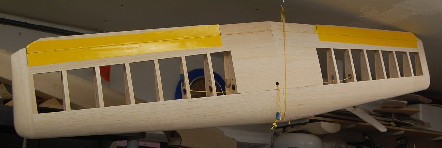
Those bright yellow strips are home made gapless hinges. They are just two strips of Solartex sewn together. The ailerons are beveled to hinge at the upper surface and the seam sits on the hinge point. You just cover over the top of the Solartex and then cut the ends of the aileron free. I can't take credit for the idea, it used to be a commercially available product. The wing tips have been added and you can see the small hole in the center section for the aileron Y-harness.
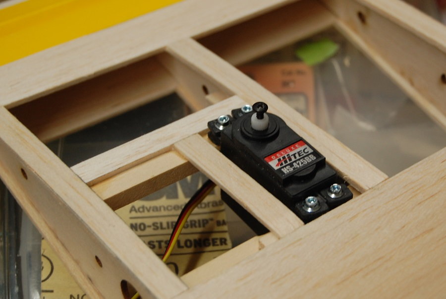
Just a simple aileron servo mount. The front part of the mount is glued directly to the lower wing spar. The aft servo rail is glued to the wing rib and is supported by two pieces of 1/4 inch square stock. Looking back it would have been much neater to have just notched the ribs so that the rail would fit flush with the top of the rib. The yellow cord is just there to help with pulling the servo leads when the time comes.
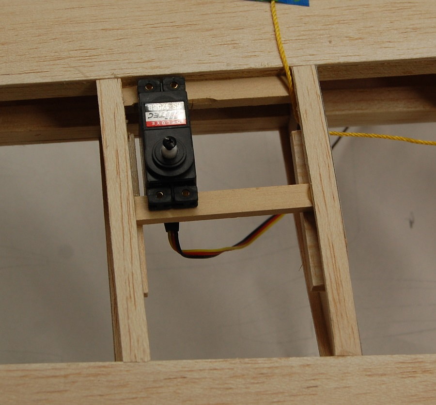
The servo now has a little filler material around it for attaching the covering. It is just more 3/32 cap strip material and it sits flush with the surface of the wing. There is plenty of room in the wing to mount the servo entirely in the wing. If this were a scale airplane that is the way I would go but in this case I prefer to have easy access to the aileron linkage.
It doesn't show well in this photo but the center section has been glassed. I used two layers of lightweight fiberglass on top and bottom of the wing. This along with the carbon fiber spar joint reinforcement ought to be quite strong. Also seen is the wing plate that fairs in the rear of the wing to the fuselage. It is 1/16 inch ply and stiffens the trailing edge. As noted earlier I am going with 1/4-20 nylon screws rather than the 6-32 screws and blind nuts described on the plans. If you look at the upper right of the photo you can see the end of the landing gear mount. There is a gap in the sheeting. This will be filled in with a bit of 1/16 sheet to provide a flush surface for attaching the covering. The grooved landing gear stock that I had on hand was different thickness than that used on the prototype model. If a flush surface is desired the blocks could either be trimmed to sit flush with the tops of the ribs and sheeted over or additional material could be added to the tops of the blocks and sanded flush with the sheeting.

Those bright yellow strips are home made gapless hinges. They are just two strips of Solartex sewn together. The ailerons are beveled to hinge at the upper surface and the seam sits on the hinge point. You just cover over the top of the Solartex and then cut the ends of the aileron free. I can't take credit for the idea, it used to be a commercially available product. The wing tips have been added and you can see the small hole in the center section for the aileron Y-harness.
Just a simple aileron servo mount. The front part of the mount is glued directly to the lower wing spar. The aft servo rail is glued to the wing rib and is supported by two pieces of 1/4 inch square stock. Looking back it would have been much neater to have just notched the ribs so that the rail would fit flush with the top of the rib. The yellow cord is just there to help with pulling the servo leads when the time comes.
The servo now has a little filler material around it for attaching the covering. It is just more 3/32 cap strip material and it sits flush with the surface of the wing. There is plenty of room in the wing to mount the servo entirely in the wing. If this were a scale airplane that is the way I would go but in this case I prefer to have easy access to the aileron linkage.
It doesn't show well in this photo but the center section has been glassed. I used two layers of lightweight fiberglass on top and bottom of the wing. This along with the carbon fiber spar joint reinforcement ought to be quite strong. Also seen is the wing plate that fairs in the rear of the wing to the fuselage. It is 1/16 inch ply and stiffens the trailing edge. As noted earlier I am going with 1/4-20 nylon screws rather than the 6-32 screws and blind nuts described on the plans. If you look at the upper right of the photo you can see the end of the landing gear mount. There is a gap in the sheeting. This will be filled in with a bit of 1/16 sheet to provide a flush surface for attaching the covering. The grooved landing gear stock that I had on hand was different thickness than that used on the prototype model. If a flush surface is desired the blocks could either be trimmed to sit flush with the tops of the ribs and sheeted over or additional material could be added to the tops of the blocks and sanded flush with the sheeting.
 05-31-2019, 09:28 AM
#64
Thread Starter
LOL The Kaos is actually a pretty straightforward model to build. If you can build an Ugly Stick, you can build a Kaos. The expertise is in the airfoil and the proportions rather than in any intricate structure. Also I'm freshly retired so I have a little more time to throw at it.
05-31-2019, 05:29 PM
#66
Things are looking great Matt. I bought a preowned model with something like solartex used for the full length strip ailerons. It kept the ailerons dead straight for 20+ years. After the wing broke in half and it went in like a lawn dart I tested those hinges for strength. Man that stuff was super tough, very difficult to tear.
Y harness for ailerons? I wouldn't give up the ability to program differential unless I planned on using a vintage radio. Maybe you are and I missed it?
Y harness for ailerons? I wouldn't give up the ability to program differential unless I planned on using a vintage radio. Maybe you are and I missed it?
05-31-2019, 05:37 PM
#67
My Feedback: (2)
I had a conversation with the guy that runs Mikes Hobby shop in OKC this morning and he was telling me that a ultrasport will do better Knife edges than a Kaos. I was trying to sell my 60 size kit here and I havent heard from the person who was looking for one. I just might keep and get me a new 61 but i was wondering if a MAX 55AX would fly this airplane. ttl
Mike
Mike
06-01-2019, 03:13 AM
#68
I had a conversation with the guy that runs Mikes Hobby shop in OKC this morning and he was telling me that a ultrasport will do better Knife edges than a Kaos. I was trying to sell my 60 size kit here and I havent heard from the person who was looking for one. I just might keep and get me a new 61 but i was wondering if a MAX 55AX would fly this airplane. ttl
Mike
Mike
Last edited by Glowgeek; 06-01-2019 at 03:15 AM.
06-01-2019, 06:53 AM
#70
Thread Starter
Things are looking great Matt. I bought a preowned model with something like solartex used for the full length strip ailerons. It kept the ailerons dead straight for 20+ years. After the wing broke in half and it went in like a lawn dart I tested those hinges for strength. Man that stuff was super tough, very difficult to tear.
Y harness for ailerons? I wouldn't give up the ability to program differential unless I planned on using a vintage radio. Maybe you are and I missed it?
Y harness for ailerons? I wouldn't give up the ability to program differential unless I planned on using a vintage radio. Maybe you are and I missed it?
06-01-2019, 07:01 AM
#71
Thread Starter
Not a problem my friend, but did you know that you can send a private message (PM) to an individual by clicking on their name in the upper left hand corner of the post?
06-01-2019, 07:24 AM
#72
Thread Starter
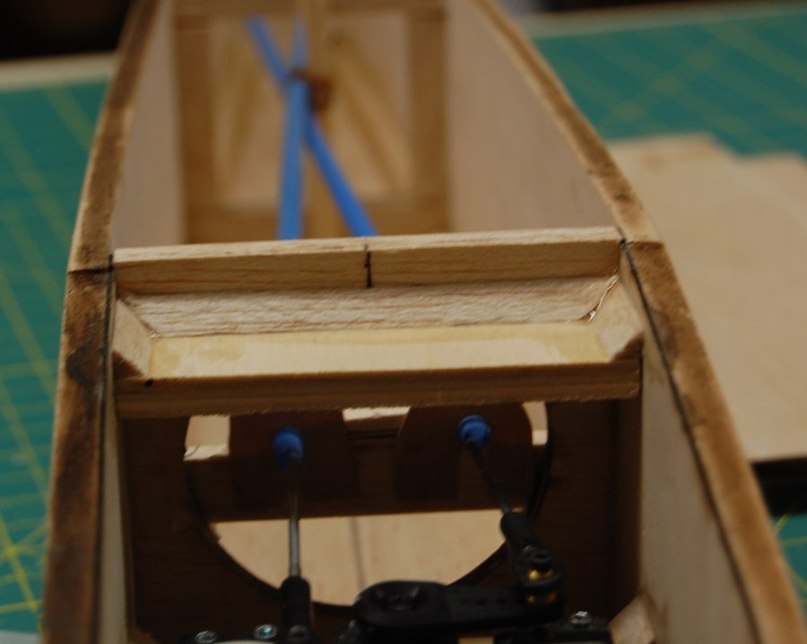
Time to start running controls through the nose. Here you can see the sleeve for the throttle push rod going through the firewall. Especially in a model with a tight fitting engine bay it is good to layout and drill as many of the holes as possible. Even with that you may have to rework holes such as the one for the throttle sheath where it passes through some of the triangle stock on the back side of the firewall.
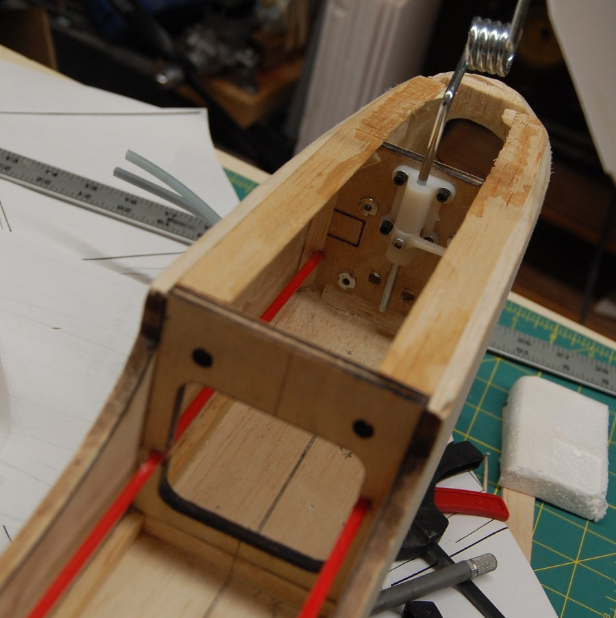
The rear of the fuel tank will protrude through the opening in the F2 former. To provide clearance, the sides of the former were notched for the throttle and nose gear push rods.
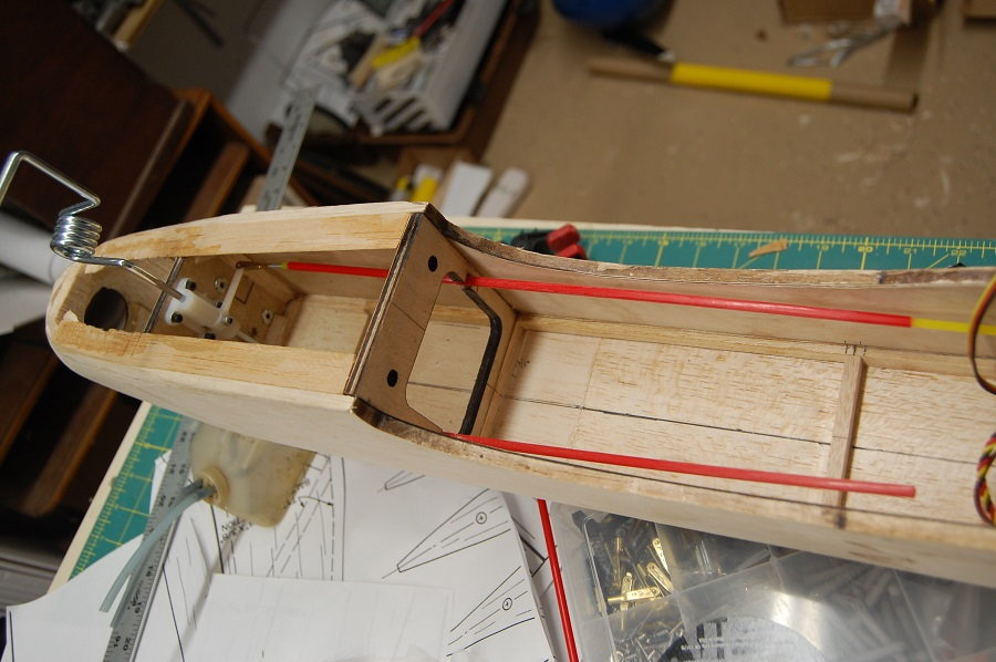
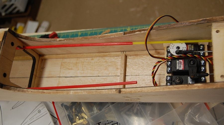
Here the push rods can be seen extending to their respective servos. The push rods will get some extra support to keep them from flopping around. The HS 645MG servo on the elevator is pretty massive overkill in terms of torque but it was on hand.
The rear of the fuel tank will protrude through the opening in the F2 former. To provide clearance, the sides of the former were notched for the throttle and nose gear push rods.
Here the push rods can be seen extending to their respective servos. The push rods will get some extra support to keep them from flopping around. The HS 645MG servo on the elevator is pretty massive overkill in terms of torque but it was on hand.
06-01-2019, 07:55 AM
#73
Matt, looking great. Did you use a wire bender/coiler to make the the nose gear strut or buy it that way?
On those nose wheel/rudder combo servos do you mechanically set up the nose wheel to have considerably less travel than the rudder? Seems to help a lot for high speed ground handling on take off and landings.
To get a perfect fit of the wing into the wing saddles I apply a thin layer of epoxy/micro balloons to the uncovered fuse wing saddles followed by a strips of wax paper and then tighten down the covered wing with the wing bolts. Once things cure and a little sanding flush on the inside and outside the fuse is ready to cover. The wax paper is slightly thicker than film coverings but not enough to notice a gap. The hardest part using that trick is making sure there are no wrinkles in the wax paper strips when tightening down the wing.
06-01-2019, 11:42 AM
#74
Thread Starter
Matt, looking great. Did you use a wire bender/coiler to make the the nose gear strut or buy it that way?
On those nose wheel/rudder combo servos do you mechanically set up the nose wheel to have considerably less travel than the rudder? Seems to help a lot for high speed ground handling on take off and landings.
To get a perfect fit of the wing into the wing saddles I apply a thin layer of epoxy/micro balloons to the uncovered fuse wing saddles followed by a strips of wax paper and then tighten down the covered wing with the wing bolts. Once things cure and a little sanding flush on the inside and outside the fuse is ready to cover. The wax paper is slightly thicker than film coverings but not enough to notice a gap. The hardest part using that trick is making sure there are no wrinkles in the wax paper strips when tightening down the wing.
On those nose wheel/rudder combo servos do you mechanically set up the nose wheel to have considerably less travel than the rudder? Seems to help a lot for high speed ground handling on take off and landings.
To get a perfect fit of the wing into the wing saddles I apply a thin layer of epoxy/micro balloons to the uncovered fuse wing saddles followed by a strips of wax paper and then tighten down the covered wing with the wing bolts. Once things cure and a little sanding flush on the inside and outside the fuse is ready to cover. The wax paper is slightly thicker than film coverings but not enough to notice a gap. The hardest part using that trick is making sure there are no wrinkles in the wax paper strips when tightening down the wing.
Additional: Sullivan still shows the nose gear on their website.
Last edited by mgnostic; 06-02-2019 at 06:53 AM.
06-02-2019, 07:01 AM
#75
Thread Starter
A view of the wing mounting plate. It's a little fuzzy in the back. I should have moved the camera back and zoomed more for better depth of field. At any rate it shows the nylon screw that i am using instead of the 6-32 screws with washers described on the plans. The wing taper results in the difference between the trailing edge of the wing and the trailing edge of the plate. The plate fits up to the sheeting on the bottom of the fuselage.