


Super Kaos from Lazerworks Short Kit.
 05-03-2019, 07:12 PM
#1

Thread Starter

This fall my local club, Wichita Falls Remote Control Club, will be holding it's second Senior Pattern Association event. Last year at the club's and my first SPA contest I flew an ARF in in an informal Introductory Class flying the novice maneuvers but allowing you to use whatever airplane you had on hand. This year I'm stepping up to an actual pattern plane. Despite flying for over 30 years I've never owned an actual pattern plane. Having said that, I know that a lot of airplanes including the aforementioned ARF have pattern plane DNA. In fact that ARF isn't too many tweaks away from being a pattern plane. The SPA is a nifty way to get into aerobatic competition. Aircraft are limited to designs from 1979 or earlier. Engines are limited to .60 ci for 2-strokes, .95 for glow four strokes and .91 gasoline engines. Electrics are also allowed and one of our club members competes with an electric in Expert class. Older designs, along with rules against retracts or tuned pipes keep the planes simple and relatively inexpensive. If you are interested the SPA has a nice website with an extensive list of eligible designs.
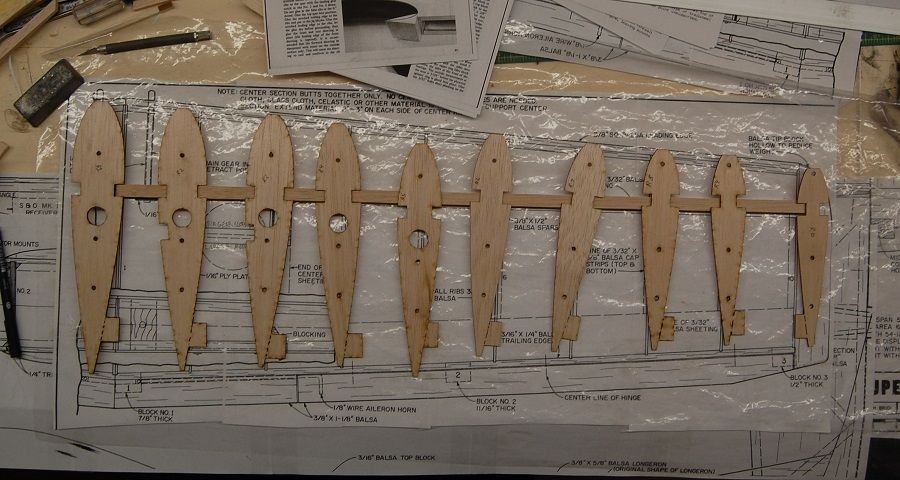
When it came time to pick a design I looked back to my first flight on a buddy box. That first flight was with a Kaos and I've had the intention of having something from the Kaos family ever since. After consulting the website at lazer-works.com I settled on a Super Kaos and had Eddie cut me a short kit. I will be building to the RCM plans as designed by Joe Bridi. There will be a few deviations from the original plans/build article to allow for the benefits of laser cutting and more modern radios and I will try to remember to make note of them.
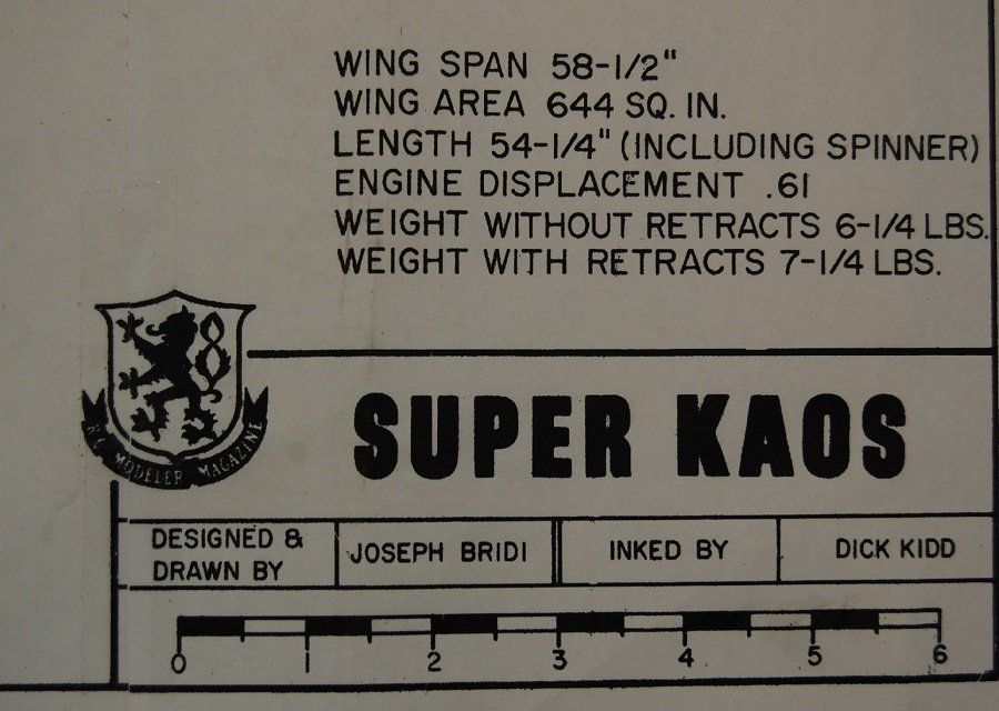
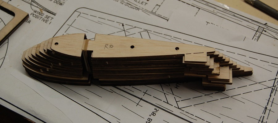
The photos above show the ribs and some of the other laser cut parts that come with the short kit. Also included are parts for the vertical tail and rudder, fuselage sides and optional fuselage doublers.
When it came time to pick a design I looked back to my first flight on a buddy box. That first flight was with a Kaos and I've had the intention of having something from the Kaos family ever since. After consulting the website at lazer-works.com I settled on a Super Kaos and had Eddie cut me a short kit. I will be building to the RCM plans as designed by Joe Bridi. There will be a few deviations from the original plans/build article to allow for the benefits of laser cutting and more modern radios and I will try to remember to make note of them.
The photos above show the ribs and some of the other laser cut parts that come with the short kit. Also included are parts for the vertical tail and rudder, fuselage sides and optional fuselage doublers.

The following users liked this post:
scottrc (01-14-2021)
05-04-2019, 04:36 AM
#2
My Feedback: (20)
Build it straight and you will be rewarded with a really great flying model. I have had at least half a dozen Kaos variants and currently fly what I call a "Sorta Kaos." It is a combination of features from from several variants that started with foam cores labeled "Kaos" and the plans for the original Kaos.
Chuck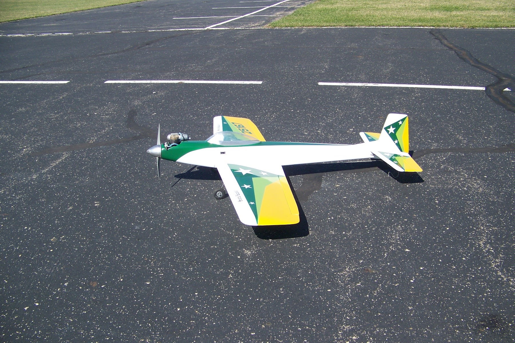
Chuck
The following users liked this post:
scottrc (01-14-2021)
05-04-2019, 06:53 AM
#3
Thread Starter
Hi Chuck, good looking airplane. Building straight is definitely the secret to building a good aerobatic plane. There are some things to point out as construction proceeds but the Super Kaos is really a pretty straightforward design. I went to an SPA event near Ft Worth on April 27 and saw several variations on the Kaos theme. If you start counting all of the Kaos variants and airplanes that borrowed some Kaos design elements you run out of fingers pretty quickly.
05-05-2019, 07:33 AM
#4
Thread Starter
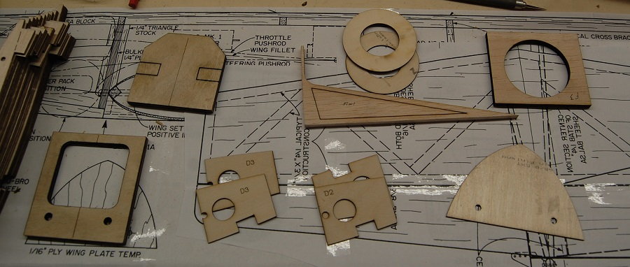
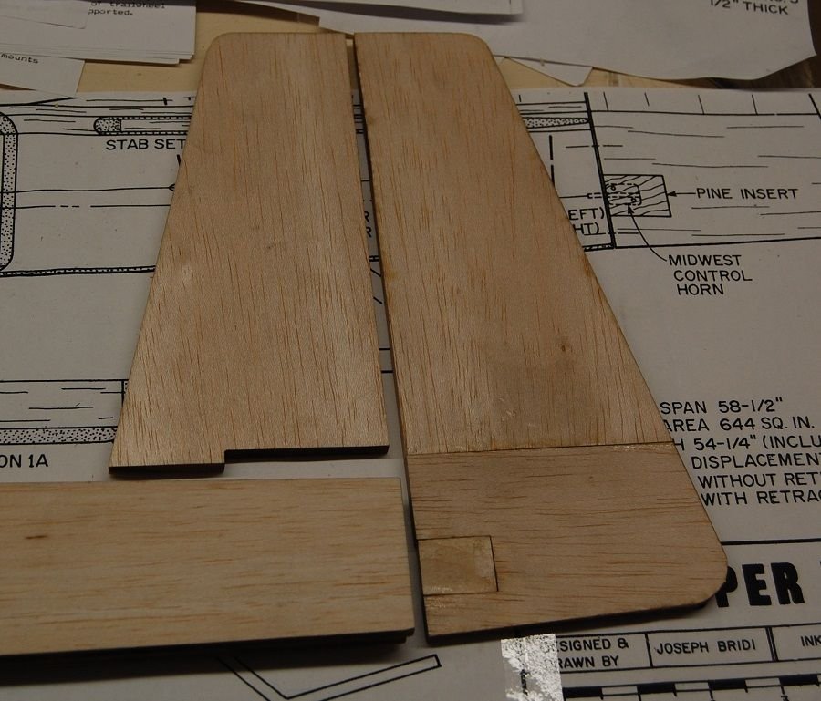
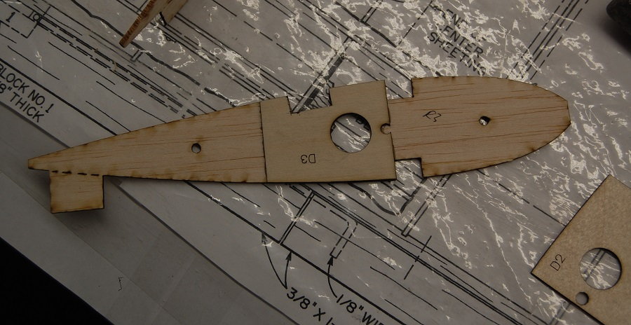
Here are some more photos of the laser cut parts. You can see the joint between the front and rear sections of the fuselage. The fit is exact and the critical line along the top of the fuselage side is straight.
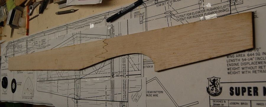
I had actually started some of the build before I settled on doing the thread so this picture includes an assembled rudder. The rudder is cut as per the plans with horizontal grain for the wood at the bottom and a laminated light ply insert for the control horn. I have the construction article from RCM magazine but it doesn't describe the reason for the insert.I suspect it is just for crush resistance. The short kit includes the insert. There is also a step on the front of the fin to inlet it into the top of the fuselage. There is also a laser cut extension for the fin included in the pack.
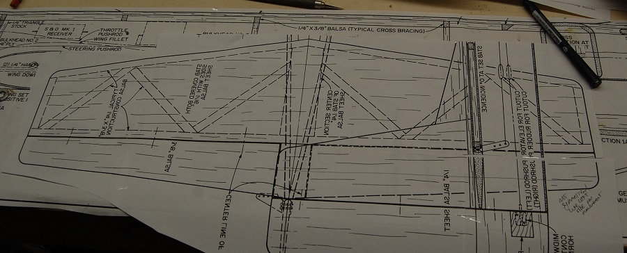
Here is a view of the plans for the horizontal tail. In comparison the the solid sheet fin and rudder the horizontal tail is a built up structure that is then sheeted with 1/16 in sheet. The elevators are cut from 3/8 balsa sheet. You may notice that the lettering on the plans for the tail is reversed. I didn't feel like making a 30 mile round trip into town and back to have the plans printed so i just used tile print. The plans, at least the ones that I have, only show the starboard wing. For convenience in building the left wing I just printed a second set of the plans after I flipped them in Inkscape. I assembled the first set of plans for building the fuselage and the tail section from the reversed set was convenient for building the horizontal tail.
I had actually started some of the build before I settled on doing the thread so this picture includes an assembled rudder. The rudder is cut as per the plans with horizontal grain for the wood at the bottom and a laminated light ply insert for the control horn. I have the construction article from RCM magazine but it doesn't describe the reason for the insert.I suspect it is just for crush resistance. The short kit includes the insert. There is also a step on the front of the fin to inlet it into the top of the fuselage. There is also a laser cut extension for the fin included in the pack.
Here is a view of the plans for the horizontal tail. In comparison the the solid sheet fin and rudder the horizontal tail is a built up structure that is then sheeted with 1/16 in sheet. The elevators are cut from 3/8 balsa sheet. You may notice that the lettering on the plans for the tail is reversed. I didn't feel like making a 30 mile round trip into town and back to have the plans printed so i just used tile print. The plans, at least the ones that I have, only show the starboard wing. For convenience in building the left wing I just printed a second set of the plans after I flipped them in Inkscape. I assembled the first set of plans for building the fuselage and the tail section from the reversed set was convenient for building the horizontal tail.
05-06-2019, 07:23 AM
#5
Thread Starter
A good place to start construction is with the horizontal tail. Start by edge gluing 1/16 inch balsa to make a top and bottom skin for the structure. I used the technique where you tape one side of the sheeting together with masking tape, fold the joint open and glue with Titebond or similar glue and then flatten the sheet and weight it down until it dries.
The frame for the horizontal tail is built out of 1/4 x 3/8 stock. Just glue it up over the plans.
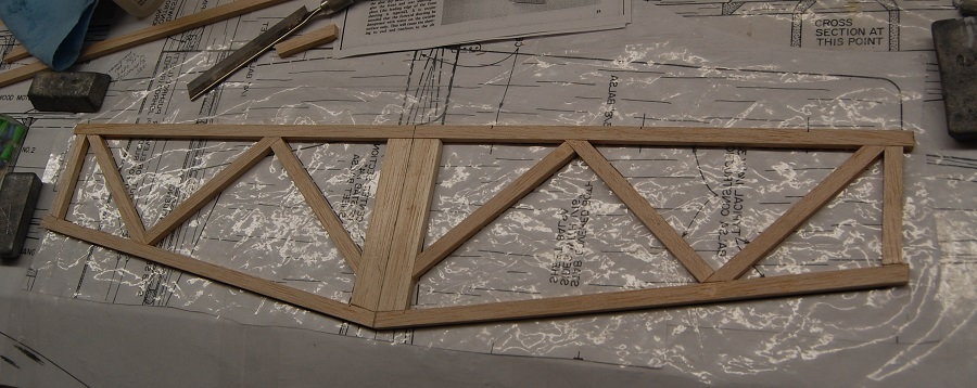
The next step is to glue the sheeting to the framework. If you build your frame on a flat surface you will get a flat frame but I like to use weights to hold everything while the glues set to keep any twists or bows from creeping in.
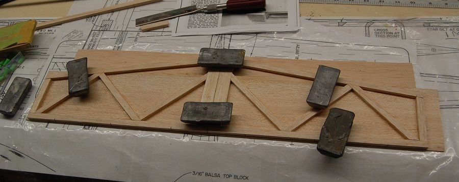
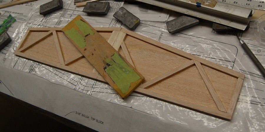
The sheeting is trimmed to the perimeter of the frame than the other side is sheeted in the same way. Both sides of the frame were sanded with a long block to make sure that there were no bumps or stray blobs of glue that would interfere with the sheeting.
The frame for the horizontal tail is built out of 1/4 x 3/8 stock. Just glue it up over the plans.
The next step is to glue the sheeting to the framework. If you build your frame on a flat surface you will get a flat frame but I like to use weights to hold everything while the glues set to keep any twists or bows from creeping in.
The sheeting is trimmed to the perimeter of the frame than the other side is sheeted in the same way. Both sides of the frame were sanded with a long block to make sure that there were no bumps or stray blobs of glue that would interfere with the sheeting.
05-08-2019, 07:30 AM
#6
Thread Starter
Leading into some wing construction, the first step is adding the doublers to the R2 and R3 ribs. One should be careful to mount the doublers correctly. The doublers for the R2 ribs go on the inboard side of the rib and the doublers for the R3 go on the outboard side. This falls under the same heading as be careful to build a right side and a left side of the fuselage. In looking at this rib and all of the others you can see small holes for and aft. The construction article mentions using the RCM wing jig that assembled the wings on rods that were held in position by the jig. If you have the jig, the holes are there but I don't have one and it isn't needed with this short kit. There are times when a jig is super handy but in this case the external jig has been replace with temporary tabs on the ribs that have been added by the kit cutter. An inconsistency that occurs in the plans shows up here. The ribs are cut exactly as they are shown on the plans. However the top view of the wing and the side view of the fuselage show a wing with a 3/8 square stock leading edge set into a notch in the front of the rib. Either the draftsman wasn't paying attention and drew in what he was used to or somebody didn't proof the plans before sending them to the magazine. From the few plans I have seen the 3/8 square LE, while functional, is different from most of the Kaos family of planes. The ribs shown on the plans and as supplied are consistent with the leading edge shown below.
This is a drawing I found on the net. It is not specifically the Kaos but it illustrates the technique that will be used.
This is a drawing I found on the net. It is not specifically the Kaos but it illustrates the technique that will be used.
05-10-2019, 06:45 PM
#7
Thread Starter
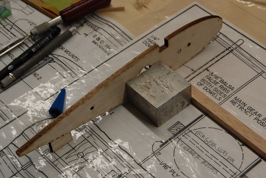
This picture shows all four of the landing gear mount rib doublers that come with the short kit. They glue to the R2 and R3 ribs on each side of the wing . these ribs are notched for the landing gear blocks. The gear block that I had was about 1/8 inch wider that what was described in the plans. I marked the doublers and ribs for notching and just widened the cut for the bear block. I try to mark every thing I am going to cut curing a step. Distractions happen and it is irritating if you get called away and forget which side of the cut out you were enlarging. The plans show tricycle gear and that I what I am going with. I have Kaoses (Kaoi? what is the plural for a Kaos?) built as tail draggers but in the case of building from a kit you would have to cut new R2 and R3 ribs and rib doublers with the landing gear cutout in front of the spar.

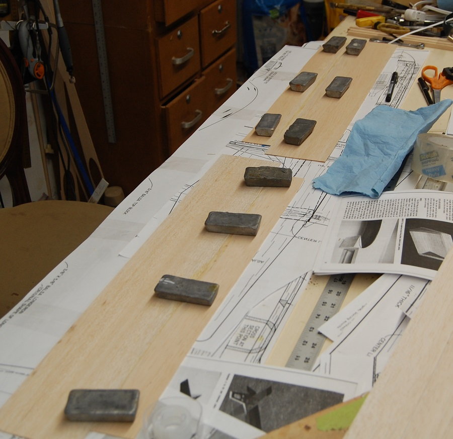
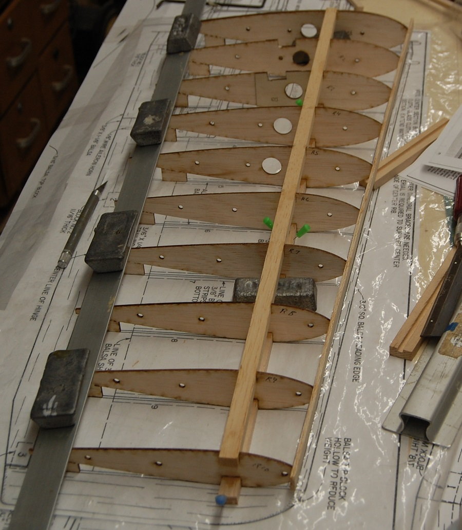
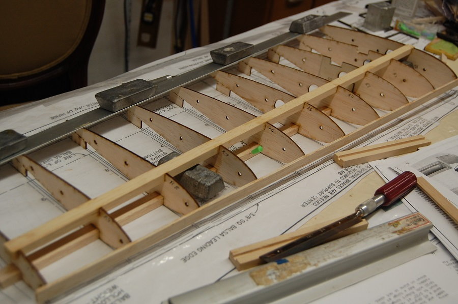
Laying out the upper wig spar. the wing is built upside down and in halves. The wing is designed and assembled in such a way that the wing is flat across the top at the spar. The taper of the wing across the span provides a small amount of dihedral as the wing decreases in thickness toward the tip of the wing. I used some nice straight hard balsa for the spars. At 3/8 x 1/2 they are fairly substantial. In my case I'm not using retractable landing gear as it is not allowed in SPA competition. The original build article shows photos of a plane with retracts and plans show the presumed location of the retractable gear but the plans have very little information. If you wanted retracts you were pretty much on your own regarding mounts and plumbing/linkages. At the top of the photo you can see some of the pages from the RCM build article. An experienced builder could get by without the article but it is handy to have for reference and it is available on the Outerzone website.

Here are the ribs laid out for the starboard wing. As described earlier, the ribs have the holes for the wing jig as well as the temporary tabs for building directly over the plans. One thing that is different from the original plans is that the root rib R1 is cut from thicker material. I didn't notice it and so didn't ask Eddie about it when I picked up the kit but the extra material would give something to work with if you needed to sand the wing rood to adjust the fit or fine tune the amount of dihedral.
The plans show tricycle gear and that I what I am going with. I have Kaoses (Kaoi? what is the plural for a Kaos?) built as tail draggers but in the case of building from a kit you would have to cut new R2 and R3 ribs and rib doublers with the landing gear cutout in front of the spar.Laying out the upper wig spar. the wing is built upside down and in halves. The wing is designed and assembled in such a way that the wing is flat across the top at the spar. The taper of the wing across the span provides a small amount of dihedral as the wing decreases in thickness toward the tip of the wing. I used some nice straight hard balsa for the spars. At 3/8 x 1/2 they are fairly substantial. In my case I'm not using retractable landing gear as it is not allowed in SPA competition. The original build article shows photos of a plane with retracts and plans show the presumed location of the retractable gear but the plans have very little information. If you wanted retracts you were pretty much on your own regarding mounts and plumbing/linkages. At the top of the photo you can see some of the pages from the RCM build article. An experienced builder could get by without the article but it is handy to have for reference and it is available on the Outerzone website.
Here are the ribs laid out for the starboard wing. As described earlier, the ribs have the holes for the wing jig as well as the temporary tabs for building directly over the plans. One thing that is different from the original plans is that the root rib R1 is cut from thicker material. I didn't notice it and so didn't ask Eddie about it when I picked up the kit but the extra material would give something to work with if you needed to sand the wing rood to adjust the fit or fine tune the amount of dihedral.
05-13-2019, 08:08 AM
#8
Thread Starter
If you look on the plans at the landing gear blocks you will see that I have made myself a note about the slots for the gear mounting blocks. One thing about building a short kit as opposed to a full kit is that you are sourcing some of the wood yourself. One advantage is that you get to pick and choose the wood that you use but where pre-cut items like landing gear block are used it is wise to check the fit on everything before you start assembly. In this case the landing gear blocks were a bit wider than those on the plan. Since several days elapsed between gathering the parts and reaching this step in the assembly I made my self a note so I wouldn't forget to adjust the parts. By the time I get done with a build I have often scribbled notes all over the plan. Cracking on with the build, you can see my right angle block. It is just a block of aluminum that has followed my around for 30 odd years. In this case the rib is square both to the table and to the spar. Here you can clearly see the additional thickness of the W-1 rib as described in the previous post. Again looking at the plans next to the W-1 rib, you can see an indication of "false ribs" on either side of the leading edge dowels. Apparently these are made of 3/16ths balsa but their shape is not shown on the plans. The article describes gluing them in place after the wing dowels are drilled and installed. Presumably they reinforce and stiffen the wing dowels and help to transfer loads to the wing spar.
Fitting all of the ribs on the wing half. Weights and a strait edge help to hold everything in place. The fit between the ribs and the spar was snug and they could be glued in by wicking thin CA into the joint. The sub leading edge was also glued on at this point. The sub LE will be trimmed and sanded to match the rib profile and will provide a gluing surface for the wing sheeting as illustrated in the earlier post.
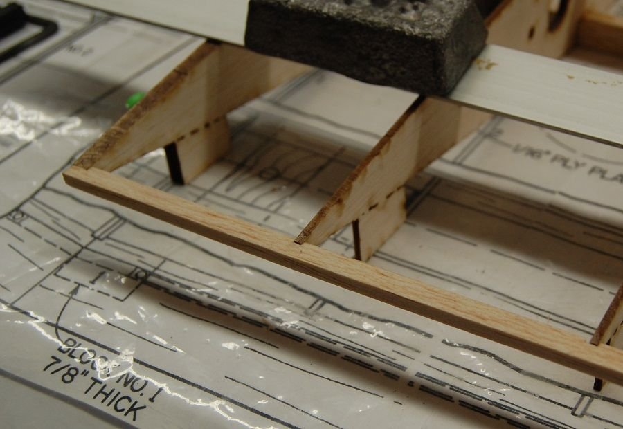
The notched trailing edge. I'm not really sure how necessary the notches are. I wonder if this isn't a design element that crept in from the production kit. The joint is overlapped top and bottom by the trailing edge sheeting so I doubt that it is an issue of strength. At any rate the notches aren't difficult to make. Just be sure that they are to the same depth so that you don't introduce any curves into the trailing edge.
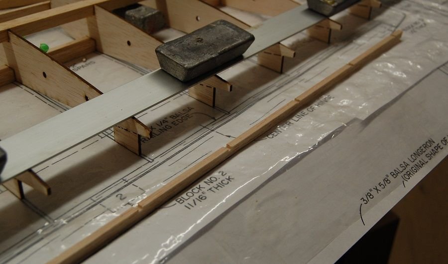
Fitting all of the ribs on the wing half. Weights and a strait edge help to hold everything in place. The fit between the ribs and the spar was snug and they could be glued in by wicking thin CA into the joint. The sub leading edge was also glued on at this point. The sub LE will be trimmed and sanded to match the rib profile and will provide a gluing surface for the wing sheeting as illustrated in the earlier post.
The notched trailing edge. I'm not really sure how necessary the notches are. I wonder if this isn't a design element that crept in from the production kit. The joint is overlapped top and bottom by the trailing edge sheeting so I doubt that it is an issue of strength. At any rate the notches aren't difficult to make. Just be sure that they are to the same depth so that you don't introduce any curves into the trailing edge.
05-13-2019, 08:12 AM
#9
My Feedback: (2)
Hey Matt, What are going to power this bad boy with? I have a 60 size Ultra Sport that I was told was supposed to be a 40 size. I was thinking about selling it but when I get to buidling it it will be my first 60 size airplane. I still like the 25 size airplanes such as my A- Ray and the TrainAire 20.
TTL
Michael
TTL
Michael
05-13-2019, 08:18 AM
#10
Thread Starter
Hey Matt, What are going to power this bad boy with? I have a 60 size Ultra Sport that I was told was supposed to be a 40 size. I was thinking about selling it but when I get to buidling it it will be my first 60 size airplane. I still like the 25 size airplanes such as my A- Ray and the TrainAire 20.
TTL
Michael
TTL
Michael
The following users liked this post:
Propdriver (01-26-2022)
05-13-2019, 06:08 PM
#12

My Feedback: (19)
Too bad you are limited to 60 2 strokes. Engines like the OS 65 and 75 are the same physical size as the 60 and turn a much larger prop. They really wake up the older pattern planes. Any of the OS pattern engines run quite well though. Which version of the Fox do you have. Some were real dogs and some ran quite well. Duke made at least 3 different Eagle 60s over the years and there were several refinements of each version.
05-14-2019, 06:58 AM
#14
Thread Starter
Too bad you are limited to 60 2 strokes. Engines like the OS 65 and 75 are the same physical size as the 60 and turn a much larger prop. They really wake up the older pattern planes. Any of the OS pattern engines run quite well though. Which version of the Fox do you have. Some were real dogs and some ran quite well. Duke made at least 3 different Eagle 60s over the years and there were several refinements of each version.
05-14-2019, 07:03 AM
#15
Thread Starter
Thanks, It is really a pretty straightforward build. I think that this is an airplane where the sophistication came in in the design and development rather than complex building technique.
05-14-2019, 06:04 PM
#16
My Feedback: (19)
Enjoying the review. I built and flew the Super Kaos back when they first came out. Enjoyable airplane. I powered mine with several different engines including OS, Fox and Webra. The old OS Blackhead was my favorite of the bunch. I don't believe the OS 60 FSR had come out yet at the time but that was a great running engine. Keep up the good work.
05-14-2019, 07:58 PM
#17
My Feedback: (2)
Matt, I have two 40 size Tower Hobbies Kaos's one is the Arf and the Kit which is still unbuilt after a year but I might build it this fall. I in the process of finishing the ARF and I donot like the way this airplane was built you can see how they cut corners in the construction and the hardware that it comes with is crap. But I hope to be fly the ARF soon and maybee I the kit later this year. Take Care
Michael
Michael
05-15-2019, 07:38 AM
#18
Thread Starter
Matt, I have two 40 size Tower Hobbies Kaos's one is the Arf and the Kit which is still unbuilt after a year but I might build it this fall. I in the process of finishing the ARF and I donot like the way this airplane was built you can see how they cut corners in the construction and the hardware that it comes with is crap. But I hope to be fly the ARF soon and maybee I the kit later this year. Take Care
Michael
Michael
05-15-2019, 08:13 AM
#19
Thread Starter
Here is a photo showing the notched trailing edge in place. I just marked the locations of the notches as shown on the plans and made shallow cuts with a razor saw. As I noted earlier, i don't know that the notches are necessary but it seemed a nice touch..
Here is the port wing coming along with the false leading edge, both spars, the landing gear block and the trailing edge in place. The wire landing gear is not correct for the Kaos but the wire is the right size so I was checking the fit. The trailing edge appears to bow out at rib 9 near the tip of the wing. I may have cut that notch a little shallow but the photograph exaggerates the amount of bow. A couple of passes with a sanding bar ensured a straight trailing edge. The Lazerworks short kit has an extra hole in ribs one through five that was not in the original design. The original design used torque rods driven by a servo in the center of the wing and there isn't any reason why you couldn't do it that way. My personal preference is for a servo in each wing and the holes are for the servo leads. The linkage from servo to control surface is much more direct and although it isn't so much an issue with the Kaos, moving the servo reduces the amount of clutter in the fuselage. Servo mounting in the wing depends on your personal preferences but there is room to hide a standard servo completely inside the wing between ribs 5 and 6.
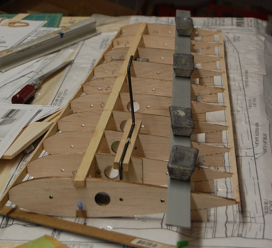
Here is the port wing coming along with the false leading edge, both spars, the landing gear block and the trailing edge in place. The wire landing gear is not correct for the Kaos but the wire is the right size so I was checking the fit. The trailing edge appears to bow out at rib 9 near the tip of the wing. I may have cut that notch a little shallow but the photograph exaggerates the amount of bow. A couple of passes with a sanding bar ensured a straight trailing edge. The Lazerworks short kit has an extra hole in ribs one through five that was not in the original design. The original design used torque rods driven by a servo in the center of the wing and there isn't any reason why you couldn't do it that way. My personal preference is for a servo in each wing and the holes are for the servo leads. The linkage from servo to control surface is much more direct and although it isn't so much an issue with the Kaos, moving the servo reduces the amount of clutter in the fuselage. Servo mounting in the wing depends on your personal preferences but there is room to hide a standard servo completely inside the wing between ribs 5 and 6.
05-15-2019, 02:51 PM
#21
My Feedback: (19)
None of mine ever butted against the center rib with them being assembled exactly as shown in the photo. Many times there were plywood reinforcements, full or partial ply ribs, etc. I never had a failure on a trike geared plane as the stresses are not as high on the main gear as they might be if was a taildragger. I like to see the LG blocks spanning at least three ribs though.
Last edited by Truckracer; 05-15-2019 at 02:53 PM.
05-16-2019, 02:42 AM
#22
None of mine ever butted against the center rib with them being assembled exactly as shown in the photo. Many times there were plywood reinforcements, full or partial ply ribs, etc. I never had a failure on a trike geared plane as the stresses are not as high on the main gear as they might be if was a taildragger. I like to see the LG blocks spanning at least three ribs though.
05-16-2019, 07:01 AM
#23
Thread Starter
With regard to the landing gear blocks; They aren't done yet. There is a plywood doubler on the R2 and R3 ribs that reaches to the spar. There will also be an anti-rotation block for the inner leg of the gear that glues to the inside of R2 and a bit of triangle stock on the outside of R3. The ribs are also tied together by 3/32 wing sheeting on the top and bottom that extends to the end of the gear block. The horizontal length of the gear wire functions as a torsion bar spring that can take a lot of flex without deforming. I will grant that it is possible to break anything and I have been told that I could tear up an anvil with a rubber hammer but the gear is as per the plans. It wasn't Joe Bridi's first rodeo.
05-16-2019, 07:28 AM
#24
My Feedback: (2)
I guess i m little old school as every low winger i built had some type of slotted vertical plywood block to keep it for moving on hard landings. I haven't built one in years. Even my train air which wasn't a low winger had one back in the day! cool I can wait to see what you cover scheme will be. I am going to cover my A-Ray with Metallic Red and yellow and Black Solar Film. They went out of business last year which is shame ttl MJ