Go Back  RCU Forums > RC Airplanes > RC Jets
Reload this Page >

The Skymaster Northrop T-38 Talon Project of 2019

Community
Search
Notices
RC Jets Discuss RC jets in this forum plus rc turbines and ducted fan power systems

The Skymaster Northrop T-38 Talon Project of 2019

Thread Tools
 
Search this Thread
 
Old 12-27-2018, 05:23 AM
  #26  
aehaas
Thread Starter
 
Join Date: Jan 2015
Location: Venice, FL
Posts: 256
Likes: 0
Received 4 Likes on 3 Posts
Default

Another one showing older and updated air intake scoop and my paint scheme:

Last edited by aehaas; 12-27-2018 at 05:26 AM.
Old 12-27-2018, 10:15 AM
  #27  
sysiek
My Feedback: (176)
 
sysiek's Avatar
 
Join Date: Feb 2009
Location: Chicago , IL
Posts: 2,314
Received 90 Likes on 65 Posts
Default

Thanks for let join the forum,so I’m doing some changes first to cut the inlets to allow to move the top and bottom tanks back as possible +some extra reinforcements to the elevators formers and main wings formers,make sure that they mark the elevators left and right the airfoil should be up side down the curved side down this will help the straight flight and take off with less elevator up ,this will also prevent to over stress and flutter to the elevators will post pictures with detail installation.
Old 12-27-2018, 10:21 AM
  #28  
sysiek
My Feedback: (176)
 
sysiek's Avatar
 
Join Date: Feb 2009
Location: Chicago , IL
Posts: 2,314
Received 90 Likes on 65 Posts
Default

Thanks for let join the forum,so I’m doing some changes first to cut the inlets to allow to move the top and bottom tanks back as possible +some extra reinforcements to the elevators formers and main wings formers,make sure that they mark the elevators left and right the airfoil should be up side down the curved side down this will help the straight flight and take off with less elevator up ,this will also prevent to over stress and flutter to the elevators will post pictures with detail installation.
Old 12-27-2018, 04:06 PM
  #29  
sysiek
My Feedback: (176)
 
sysiek's Avatar
 
Join Date: Feb 2009
Location: Chicago , IL
Posts: 2,314
Received 90 Likes on 65 Posts
Default


Look closely at the elevators profile right by fuselage
Old 12-27-2018, 05:58 PM
  #30  
sysiek
My Feedback: (176)
 
sysiek's Avatar
 
Join Date: Feb 2009
Location: Chicago , IL
Posts: 2,314
Received 90 Likes on 65 Posts
Default

The nose section just got the first black satin shot and some elevators section reinforcing


Old 12-28-2018, 01:00 PM
  #31  
aehaas
Thread Starter
 
Join Date: Jan 2015
Location: Venice, FL
Posts: 256
Likes: 0
Received 4 Likes on 3 Posts
Default

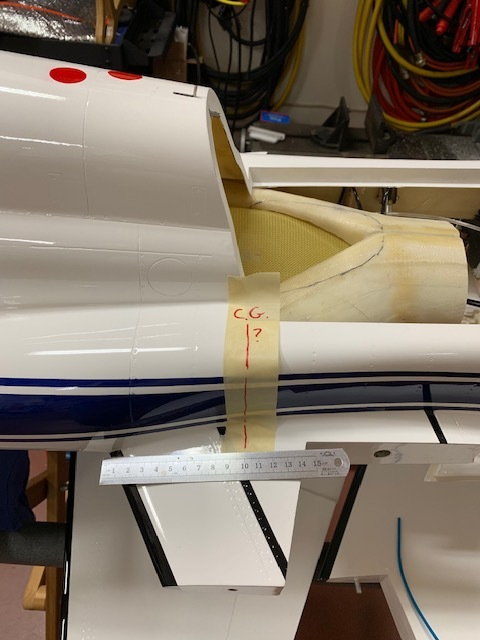
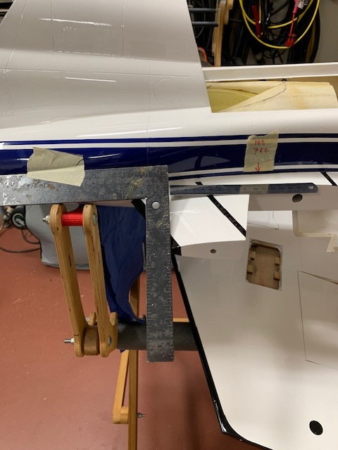
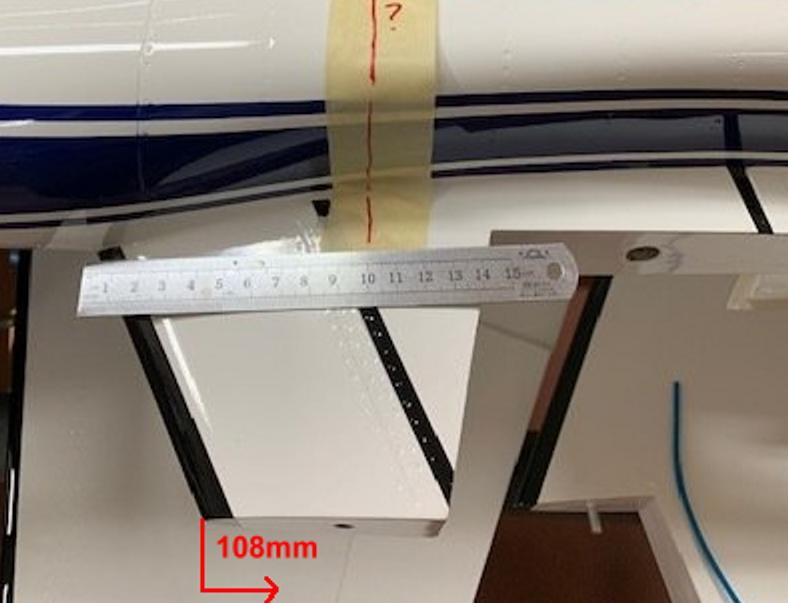
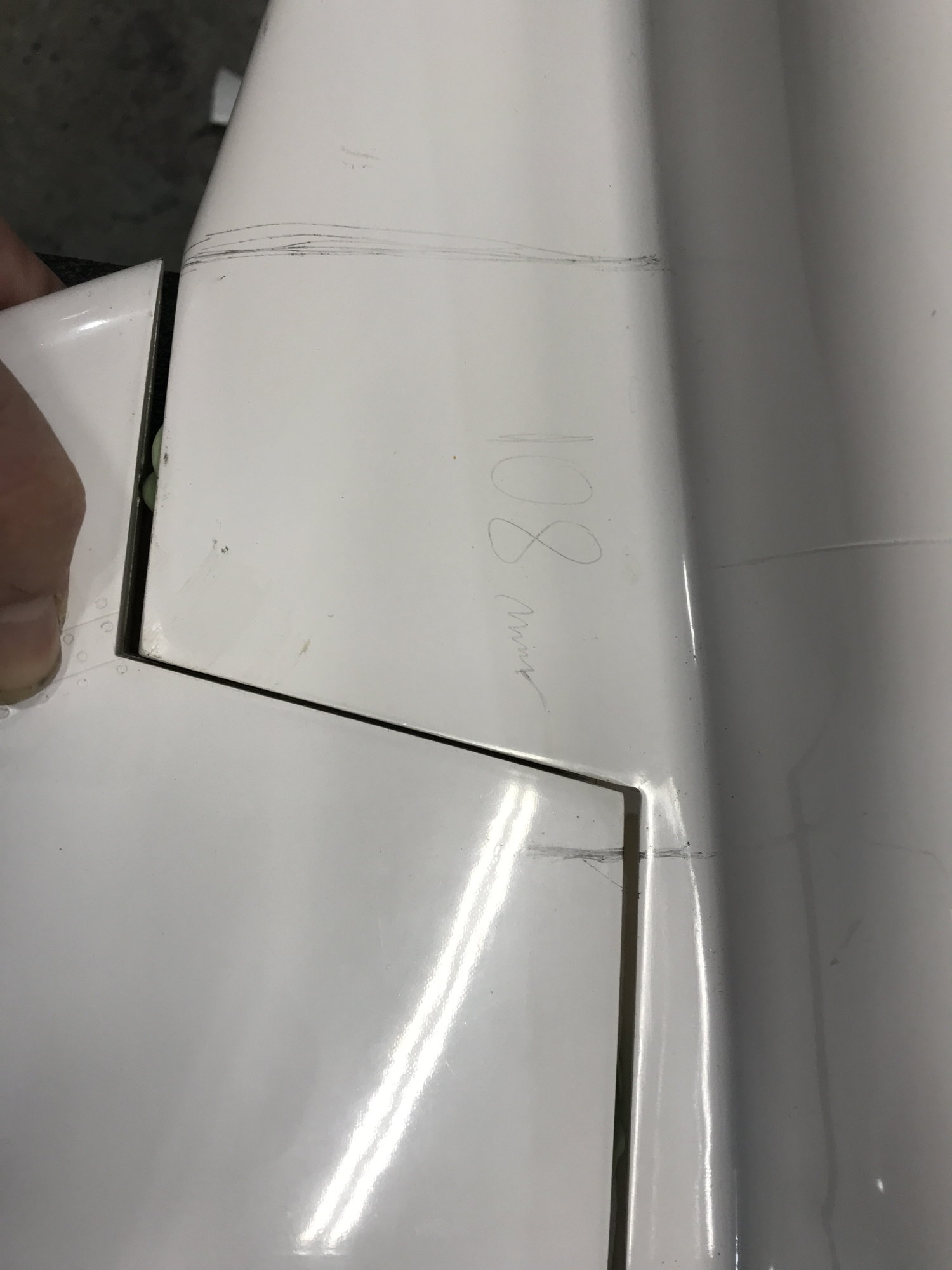
What are you guys using as the CG. The "plans" provided by Skymaster is a combination of different models. It says 90-110 mm behind the leading edge of the wing. On my model that puts it at the front bottom of the engine hatch cover. Is this correct?


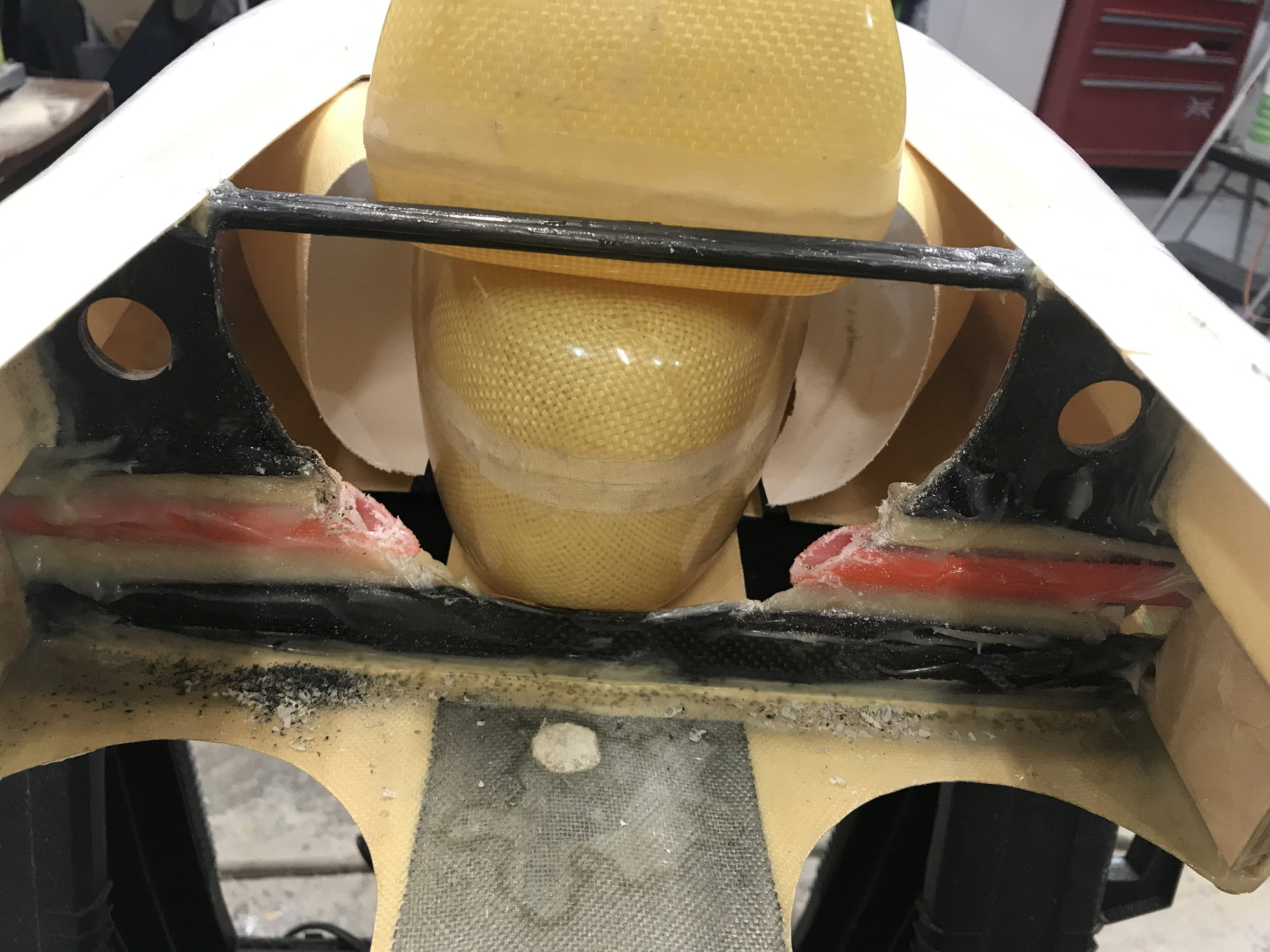
Note that I did a similar modification as Sysiek showed above to move the main fuel cell backwards somewhat so it is not all in front of the CG. I have not decided yet what to do with the small header tank provided. I'll be using the Jet-Tech fuel cell connections instead of those provided.

AEHaas
Old 12-28-2018, 01:11 PM
  #32  
sysiek
My Feedback: (176)
 
sysiek's Avatar
 
Join Date: Feb 2009
Location: Chicago , IL
Posts: 2,314
Received 90 Likes on 65 Posts
Default

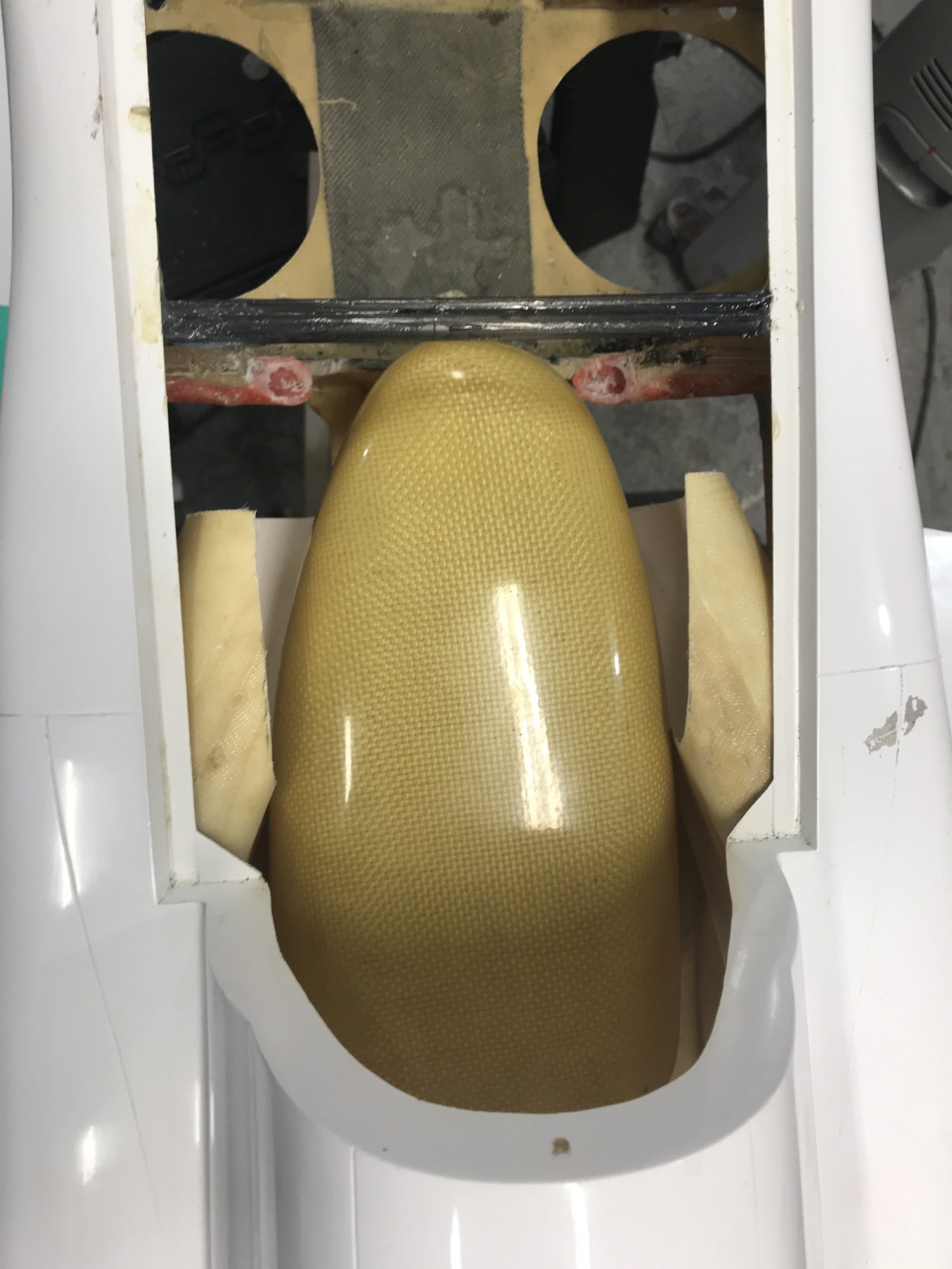
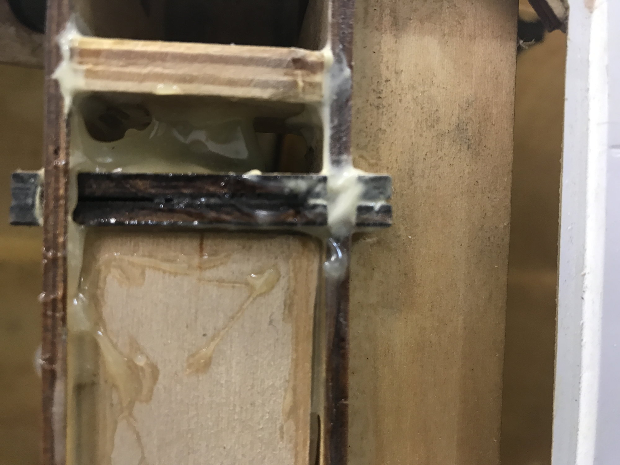
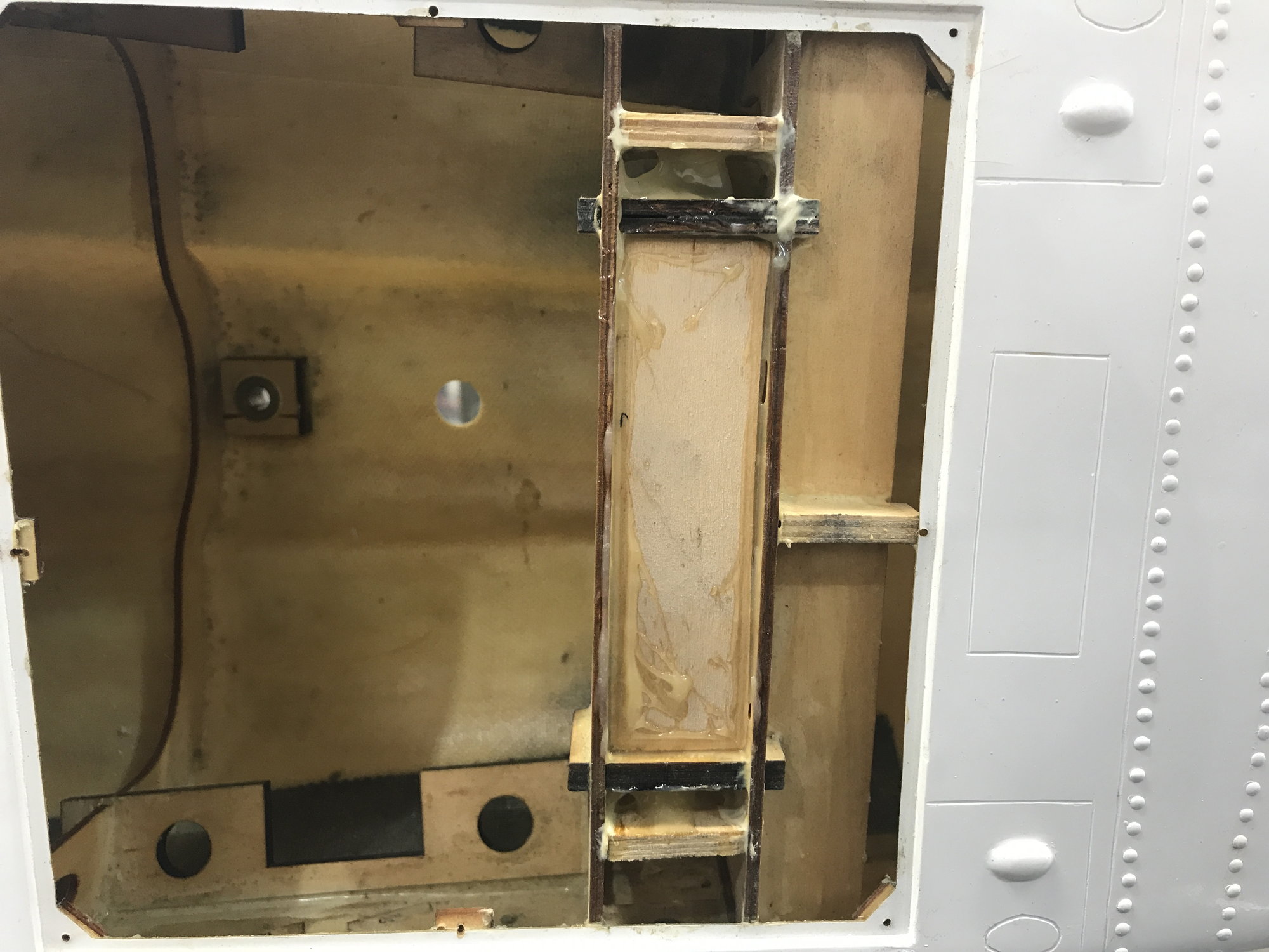
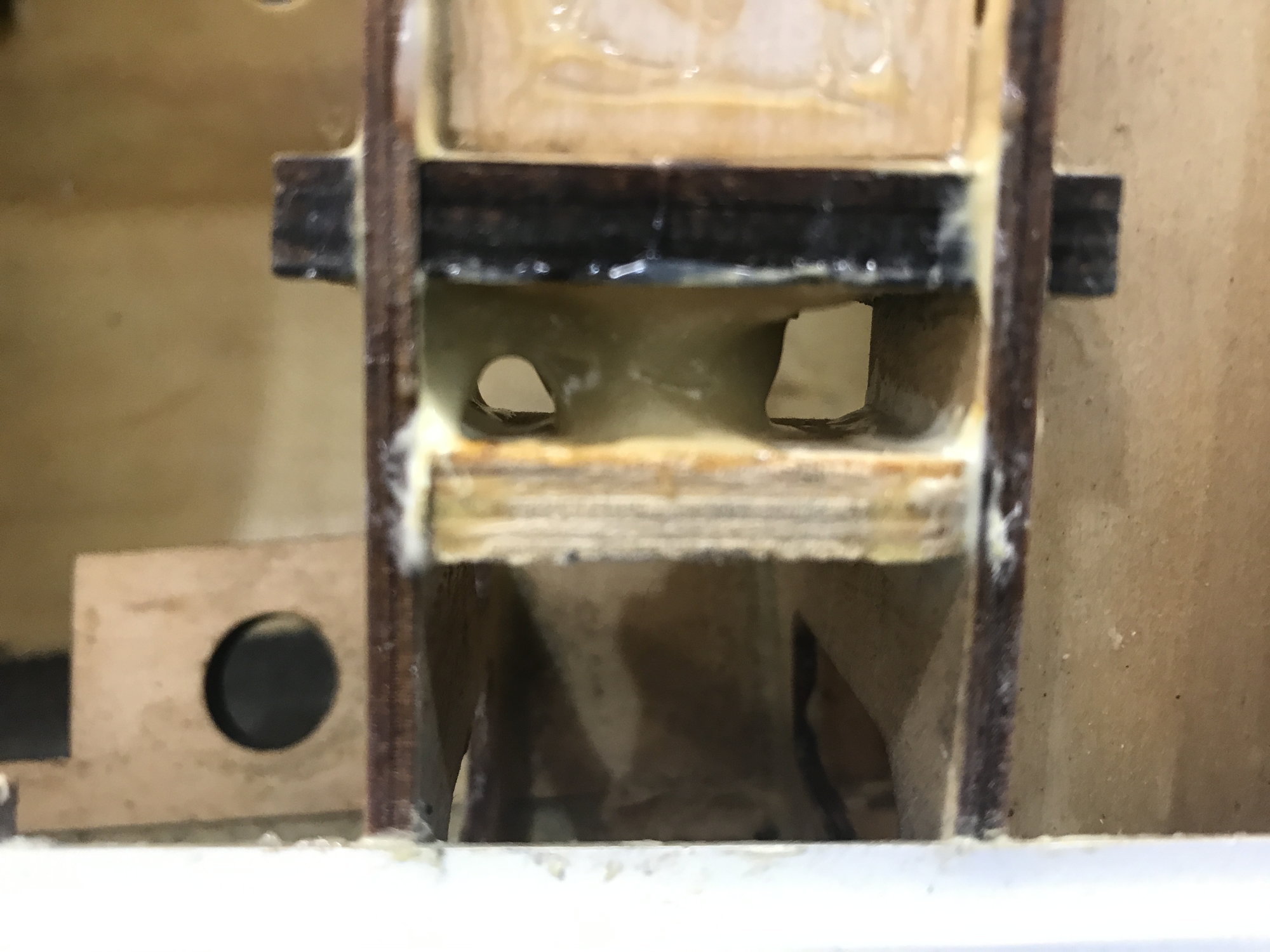
Just cut away some of the inlets and move the second tank as back as possible + you need to install a cross bar by the front wing formers this is must don’t fly this jet without it the like to flex and in some cases the former could detach from the fuselage skin this happens before on someone Jets.
Old 12-28-2018, 10:39 PM
  #33  
kevinthoele
My Feedback: (1)
 
Join Date: Feb 2002
Location: Spring, TX
Posts: 1,713
Received 40 Likes on 39 Posts
Default

I have many years flying mine and love it. CG is perfect at 108mm back from break in the leading edge of wing where the outer panel plugs in
Old 12-29-2018, 04:05 AM
  #34  
aehaas
Thread Starter
 
Join Date: Jan 2015
Location: Venice, FL
Posts: 256
Likes: 0
Received 4 Likes on 3 Posts
Default

Originally Posted by kevinthoele
I have many years flying mine and love it. CG is perfect at 108mm back from break in the leading edge of wing where the outer panel plugs in
Is it where I have the line in the picture. Yours may be 8mm behind that but it is basically at this line below, Right?? I want to be sure....

Old 12-29-2018, 06:47 AM
  #35  
kevinthoele
My Feedback: (1)
 
Join Date: Feb 2002
Location: Spring, TX
Posts: 1,713
Received 40 Likes on 39 Posts
Default

No go along the leading edge of your wing until the end of the short stub. From the leading edge at stub it is 108mm about where your ruler has 5 mark
Old 12-29-2018, 06:54 AM
  #36  
kevinthoele
My Feedback: (1)
 
Join Date: Feb 2002
Location: Spring, TX
Posts: 1,713
Received 40 Likes on 39 Posts
Default

The picture in the manual is an F5 not T38. As you can see there is a small scag of wing in front of CG line they measure from. This is similar to what I am saying on your T38
Old 12-29-2018, 07:34 AM
  #37  
aehaas
Thread Starter
 
Join Date: Jan 2015
Location: Venice, FL
Posts: 256
Likes: 0
Received 4 Likes on 3 Posts
Default

Originally Posted by kevinthoele
The picture in the manual is an F5 not T38. As you can see there is a small scag of wing in front of CG line they measure from. This is similar to what I am saying on your T38
Can you show me a picture with an obvious mark of the 108 point on your fuselage. Sorry to be of such trouble but this is the most important thing for a successful maiden and it is not at all clear to me where this point should be. I want to be 100% certain and still it is not clear to me. Call me stupid.

AEHaas
Old 12-29-2018, 07:44 AM
  #38  
aehaas
Thread Starter
 
Join Date: Jan 2015
Location: Venice, FL
Posts: 256
Likes: 0
Received 4 Likes on 3 Posts
Default

Here?

Old 12-29-2018, 09:27 AM
  #39  
kevinthoele
My Feedback: (1)
 
Join Date: Feb 2002
Location: Spring, TX
Posts: 1,713
Received 40 Likes on 39 Posts
Default

See where your square is? The point farthest away from fuse. That is where you measure from NOT next to fuse
Old 12-29-2018, 09:28 AM
  #40  
kevinthoele
My Feedback: (1)
 
Join Date: Feb 2002
Location: Spring, TX
Posts: 1,713
Received 40 Likes on 39 Posts
Default

You can call me if you would like Kevin Thoele 281-615-8455
Old 12-29-2018, 10:07 AM
  #41  
causeitflies
 
causeitflies's Avatar
 
Join Date: Jan 2003
Location: EASTERN OHIO
Posts: 2,436
Received 42 Likes on 32 Posts
Default

Originally Posted by kevinthoele
I have many years flying mine and love it. CG is perfect at 108mm back from break in the leading edge of wing where the outer panel plugs in
Kevin, I hope you bring your T-38 back to kentucky. I missed seeing it fly the last time.
Old 12-29-2018, 10:27 AM
  #42  
causeitflies
 
causeitflies's Avatar
 
Join Date: Jan 2003
Location: EASTERN OHIO
Posts: 2,436
Received 42 Likes on 32 Posts
Default

CG here...
Old 12-29-2018, 10:34 AM
  #43  
aehaas
Thread Starter
 
Join Date: Jan 2015
Location: Venice, FL
Posts: 256
Likes: 0
Received 4 Likes on 3 Posts
Default

I spoke with Kevin and confirmed his CG line here at 108mm:

Old 12-29-2018, 10:50 AM
  #44  
sysiek
My Feedback: (176)
 
sysiek's Avatar
 
Join Date: Feb 2009
Location: Chicago , IL
Posts: 2,314
Received 90 Likes on 65 Posts
Default

Will this work with the F-5? Thanks
Old 12-29-2018, 12:51 PM
  #45  
kevinthoele
My Feedback: (1)
 
Join Date: Feb 2002
Location: Spring, TX
Posts: 1,713
Received 40 Likes on 39 Posts
Default

Use the same on F5 from the drawing on plans. They measure between 90-110 so 108 is good for F5
Old 12-29-2018, 02:20 PM
  #46  
sysiek
My Feedback: (176)
 
sysiek's Avatar
 
Join Date: Feb 2009
Location: Chicago , IL
Posts: 2,314
Received 90 Likes on 65 Posts
Default


This should work
Old 12-30-2018, 04:03 AM
  #47  
jetspud
 
jetspud's Avatar
 
Join Date: Dec 2001
Location: shreveport , LA
Posts: 1,127
Received 2 Likes on 2 Posts
Default T-38

The 108 cg is we're I have mine flys great . I have bother of my tanks forward of the intakes never thought of doing what y'all did by cutting the intakes .
Old 12-30-2018, 04:11 AM
  #48  
jetspud
 
jetspud's Avatar
 
Join Date: Dec 2001
Location: shreveport , LA
Posts: 1,127
Received 2 Likes on 2 Posts
Default T-38

108 from spot B for anyone else
Old 12-30-2018, 04:12 AM
  #49  
jetspud
 
jetspud's Avatar
 
Join Date: Dec 2001
Location: shreveport , LA
Posts: 1,127
Received 2 Likes on 2 Posts
Default

Kevin helped me on that c of g also.
Old 01-05-2019, 12:43 PM
  #50  
aehaas
Thread Starter
 
Join Date: Jan 2015
Location: Venice, FL
Posts: 256
Likes: 0
Received 4 Likes on 3 Posts
Default

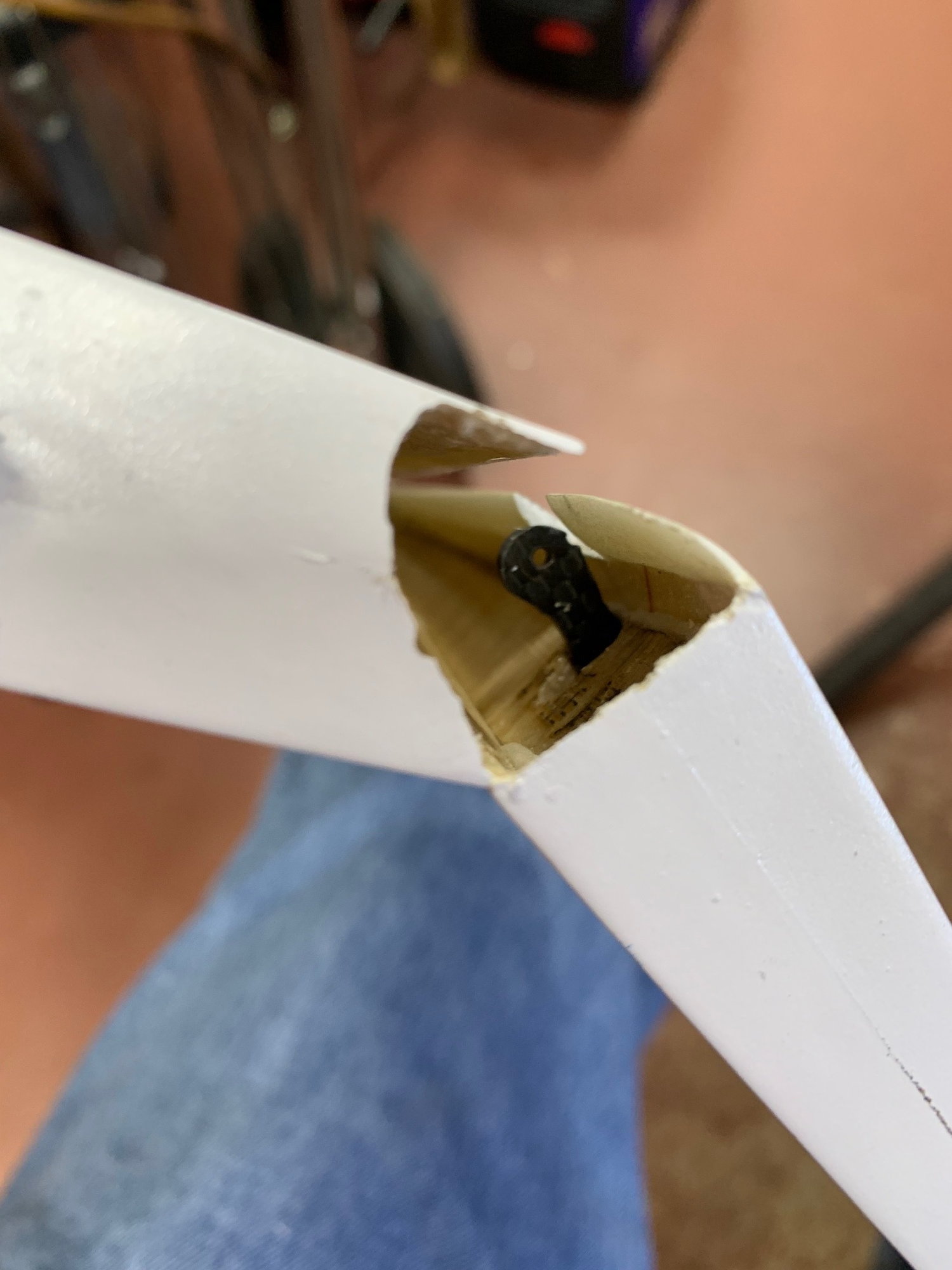
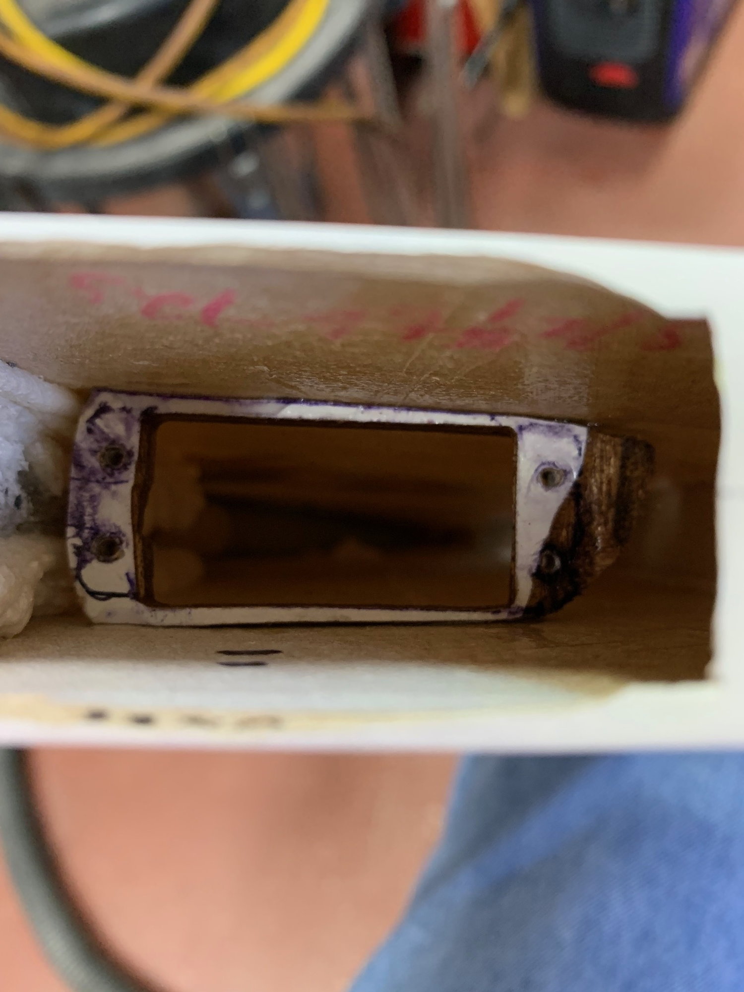
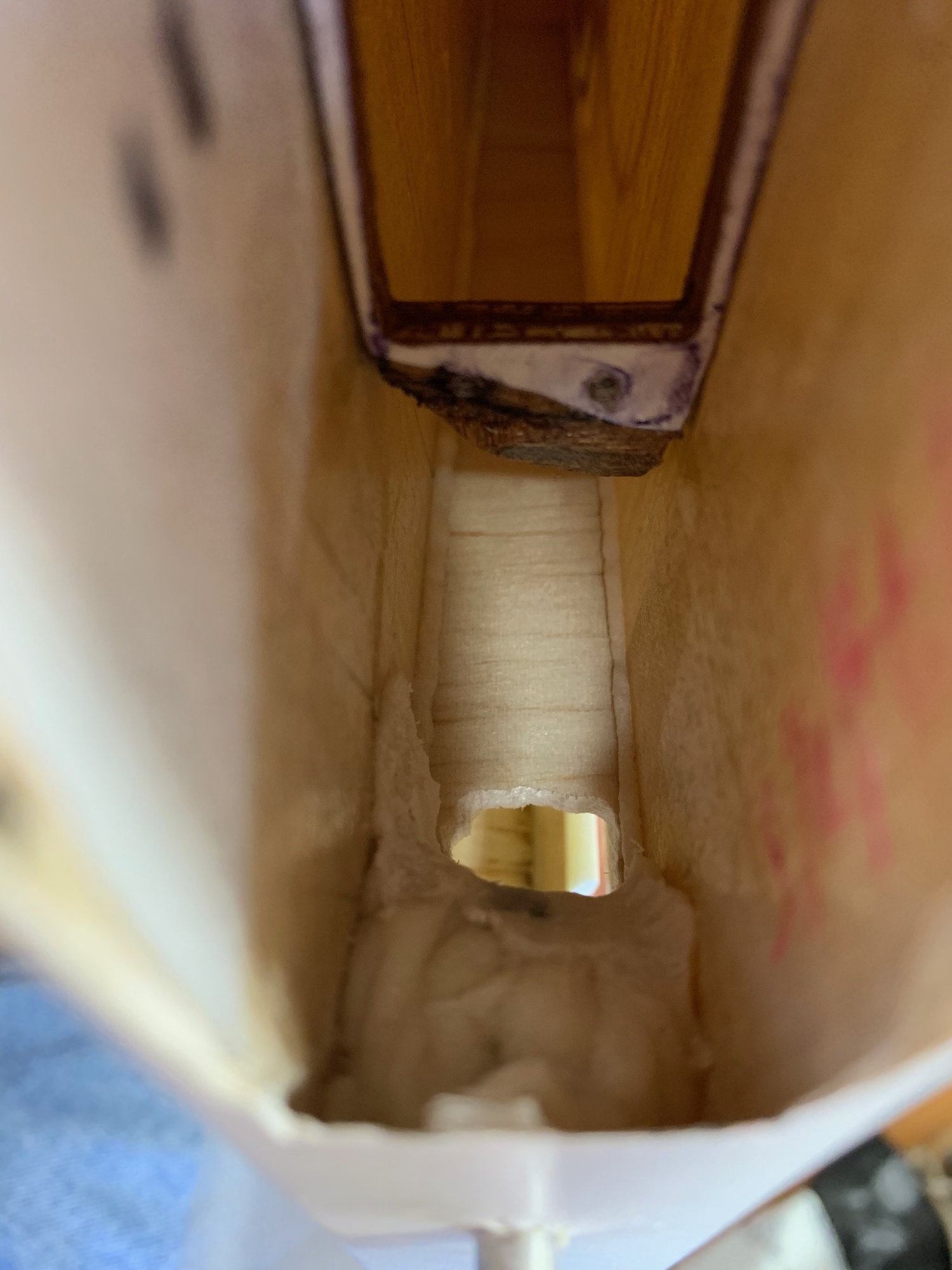
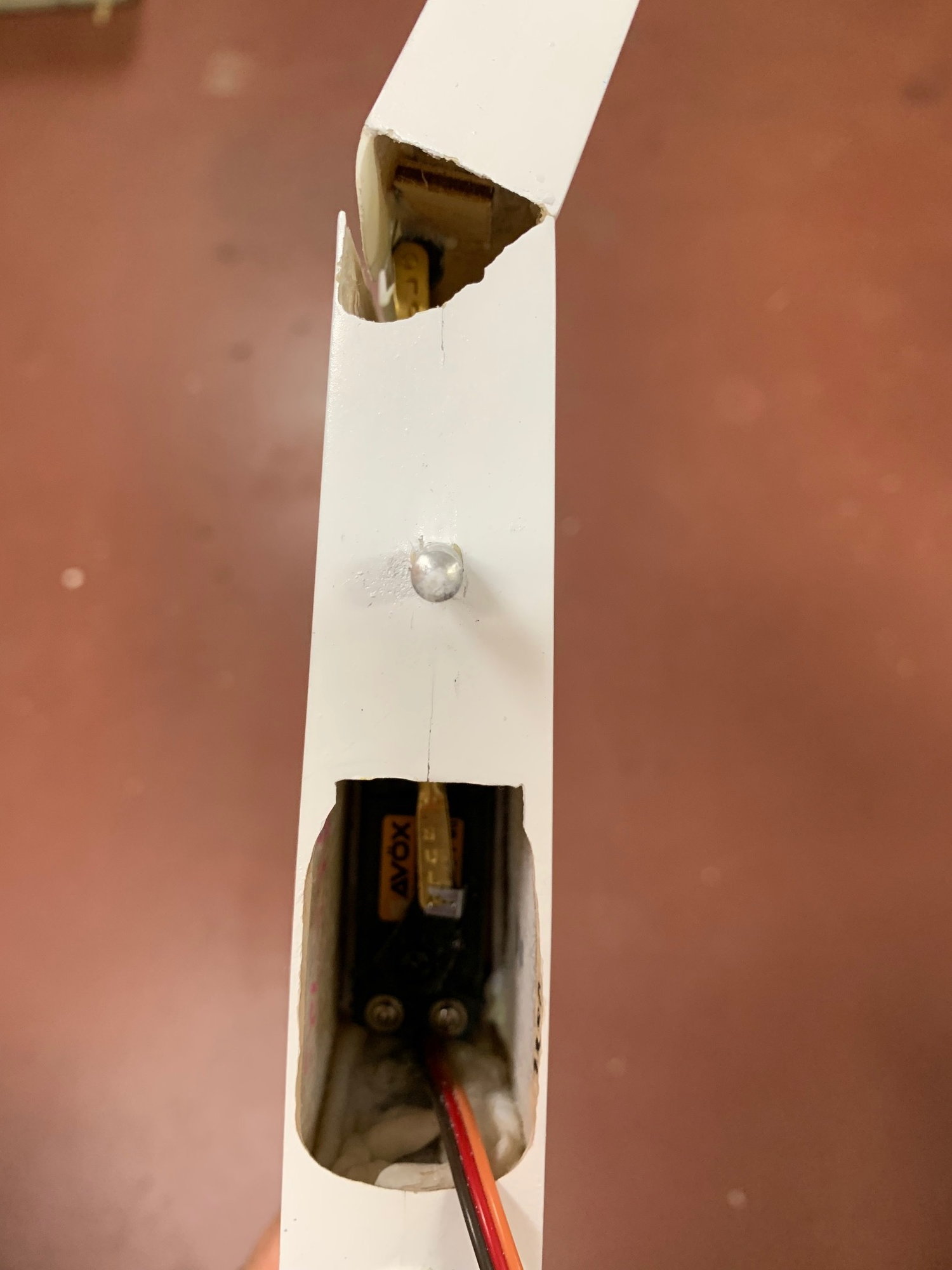
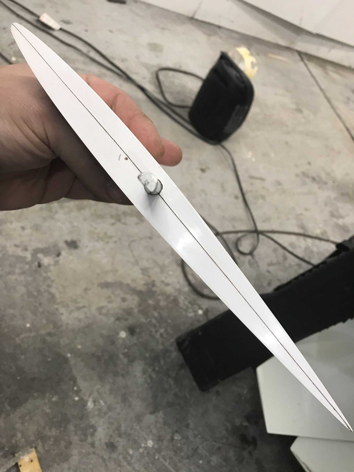
'Finished the vertical fin today with internal carbon fiber horn I made, just a piece about 1 1/2" long by about a 1/4" wide. I think it's about 1/8" thick or so. The servo tray I made sits into the fin around 1 1/4". There is a cutout on the vertical spar. I still need to reinforce the thin area that was not cut out. I did get the 2" of throw they recommend for good knife edge performance. I used the Savox SV-1254MG because it is lightweight and has plenty of torque. It has plenty as the servo arm is very short. I'll be using 6.6V LiFe batteries for the receiver and a 9.9V pack for the turbine ECU.


Contact Us - Archive - Advertising - Cookie Policy - Privacy Statement - Terms of Service -

Copyright © 2024 MH Sub I, LLC dba Internet Brands. All rights reserved. Use of this site indicates your consent to the Terms of Use.