


The Skymaster Northrop T-38 Talon Project of 2019
 01-23-2019, 11:02 AM
#76

Thread Starter
For the MPX connectors the setup is difficult at first. Once you get the hang of it there is no reason not to do this on every model. It is time consuming though.
To start with every edge of each male and female connector that faces each other is rounded. Then the housing edges are rounded where the connectors will be coming into contact during insertion/mounting the wing to the fuselage for model assembly at the field. If everything is lined up just right it is slick and quick. Everyone is amazed how I just push the wings on, tighten the bolts and off I go. No possible mess up of connections, no looking for clips to secure them.
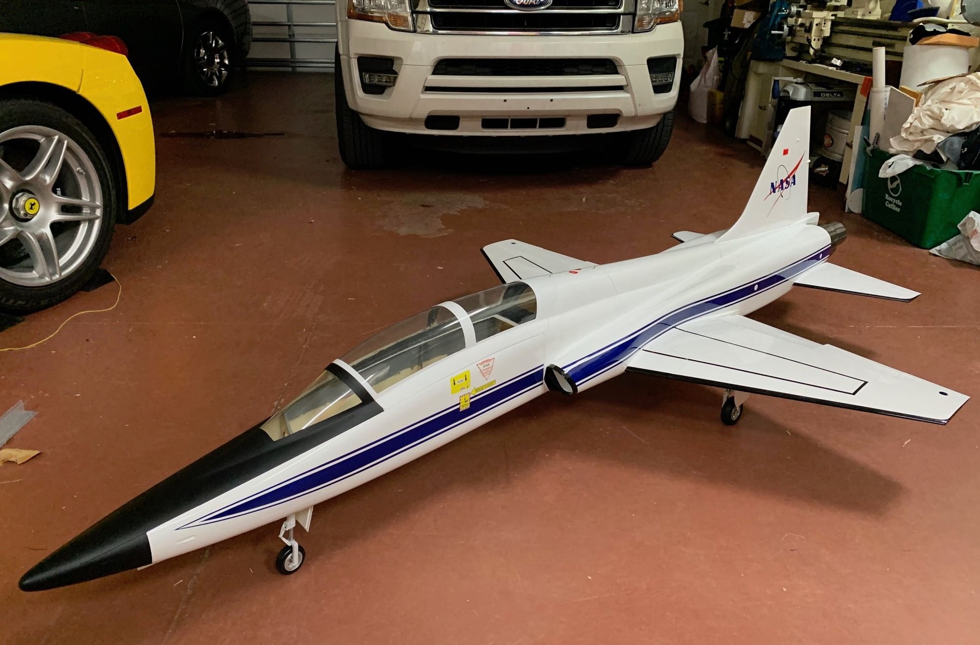
I put these on my BVM 1/6 General Dynamics Scheme F-16. I transport the plane in my Expedition with the wheels/gear down. I pull it out and put it on the table. The wings are slid on and tighten. Off I go to the startup area for fueling and an air fill:
To start with every edge of each male and female connector that faces each other is rounded. Then the housing edges are rounded where the connectors will be coming into contact during insertion/mounting the wing to the fuselage for model assembly at the field. If everything is lined up just right it is slick and quick. Everyone is amazed how I just push the wings on, tighten the bolts and off I go. No possible mess up of connections, no looking for clips to secure them.
I put these on my BVM 1/6 General Dynamics Scheme F-16. I transport the plane in my Expedition with the wheels/gear down. I pull it out and put it on the table. The wings are slid on and tighten. Off I go to the startup area for fueling and an air fill:
 01-23-2019, 11:30 AM
#77
Thread Starter
To start the mounting of the connectors You need a frame. If you have more than two servos then a double frame. Make two pairs of matching plywood frames, the holes must be very close to matching up, within a mm. These will hold the mounts for the connectors. I always put the male MPX on the wing side, no particular reason. The wing side mounts must be removable so you can solder connections for a repair or servo replacement. The problem is that the connector has no mechanism to hold it inside the mount. It would slide out when you pull the wing off the fuselage. The mount only prevents the connector from being shoved in any further.
I assemble all the mating connectors with frames and make sure they line up perfect before putting anything onto the plane.
Make a hole slightly smaller than your frame in the wing end. Glue in the frame being carful not to get adhesive onto the mount as they must be removable. Bring the wires out through the holes in the frame. go through the back of the mount and then you solder to the back of the connector.
I bend the leads on the back end of the connector, then solder my wires in place (a whole 'nother topic I will get to another time - it must be wired just right). I always tin every connection and wire end before soldering. Now shove the MPX connector into the mount all the way. I now epoxy the back end around the connector leads all over the place. Leave the lead ends that are soldered exposed though a little bit on the soldered area is not a problem. You can knife it off if you need to remake a new solder joint. Do not go beyond the edges of the mount as it has to fit back into the frame opening. When dry secure the wing mounts in place with the flat head screws. I always use a little canopy glue on screws to strengthen them while still allowing them to be removed (though with more effort).
More later on the fuselage end.
AEHaas
Last edited by aehaas; 01-23-2019 at 11:35 AM.
01-23-2019, 01:02 PM
#78
Thread Starter
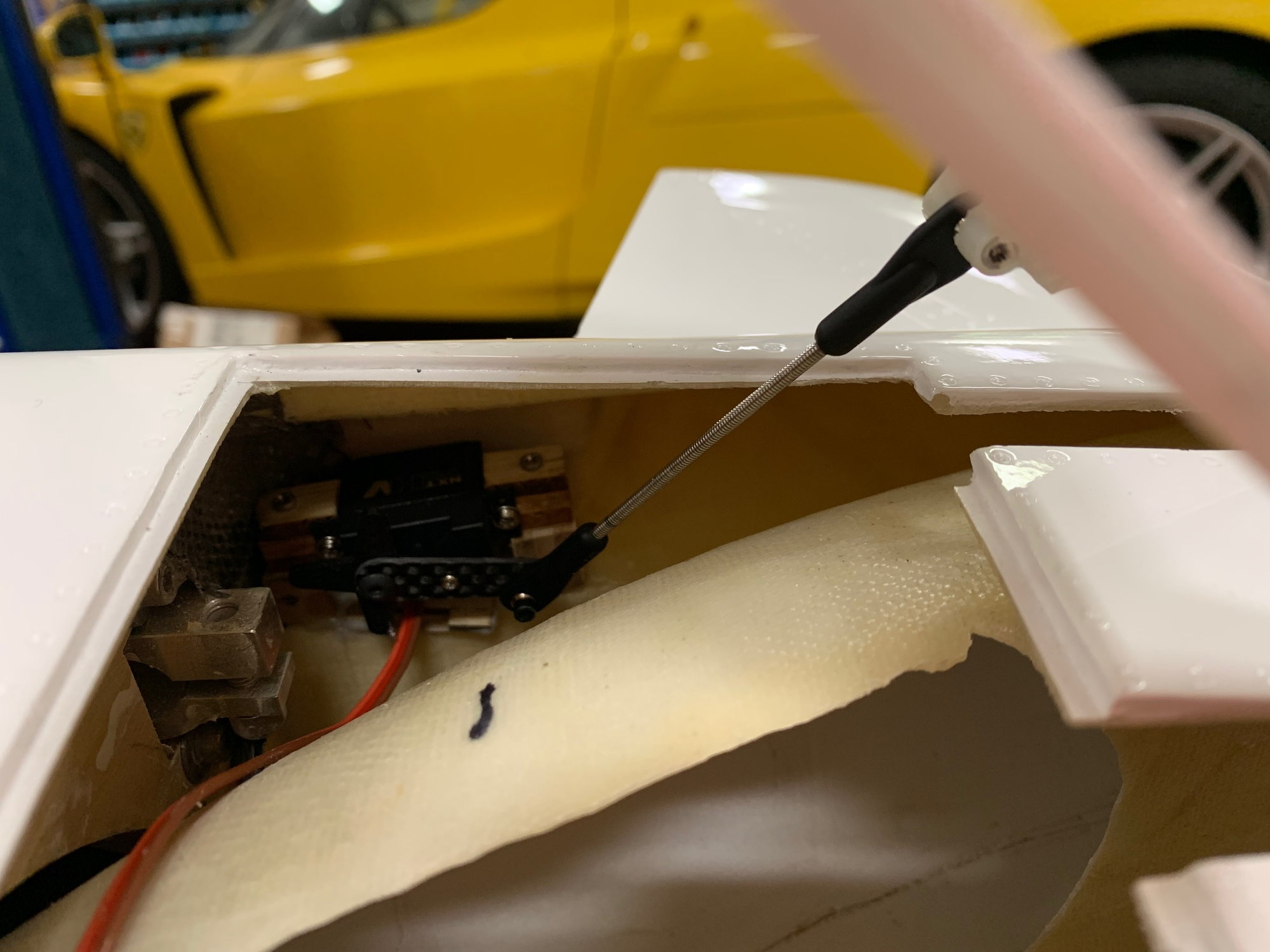
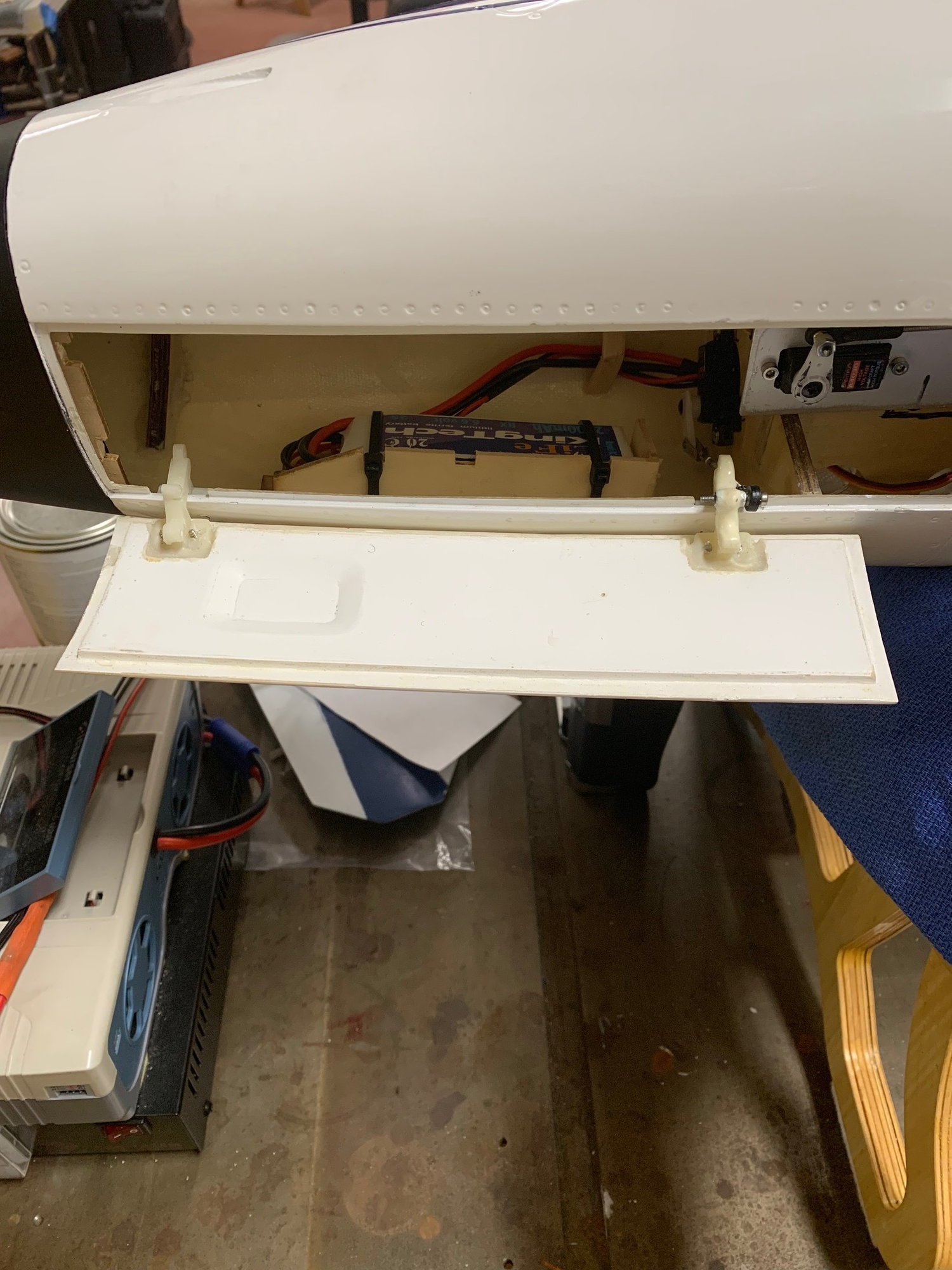
I'm about done with the air brake servos. The area was cramped but it worked out. The main thing was to be sure it was serviceable (note the recurring theme).
The air brakes only move to around 45 degrees. That is all the Skymaster installed hinges will allow. It's OK.
The air brakes only move to around 45 degrees. That is all the Skymaster installed hinges will allow. It's OK.
01-23-2019, 07:06 PM
#79
Thread Starter
Continuing on the MPX connectors: At this point you have the wing done. You can unscrew the mounting housing and pull out the connector/housing to access the solder joints if need be. The next step is to make the fuselage fit onto the wing.
Line up the wing and mark out the corresponding fuselage opening, again, making it slightly undersized to the framework of the mounts. Solder the corresponding wires to the female MPX of the fuselage after passing the wires through the opening and through the framework then housing. Pass the framework and female connectors back into the fuselage. Attach the wing to the fuselage and tighten any connections that hold the wing securely to the fuselage like you are ready to fly.
Now reach into the fuselage and push the female MPX onto the Male MPX connectors of the wing. Push the housings onto the back end of the female MPX connectors. Then slide the framework over these. The openings of the fuselage framework can be more oversized as you want it to slide easily over the female connectors. This way it is all lined up perfectly. Epoxy the ends of the connectors where you soldered the leads to prevent the MPX from sliding out of the housing when the wing is pulled off. Also epoxy the framework to the inside of the fuselage. Epoxy the housing to the framework. You will not be able to remove the housing as on the wing.
If your airplane is such that you can easily see and access the back of the female MPX you are done. You can service things if need be. If, as in the case of my F-16, the connector is in a recess that is not really accessable then you should have used a servo lead soldered to the female MPX connector. You can now disconnect from the MPX and still have easy access to connect back. Now use an appropriate servo extension to connect to the receiver. The fuselage framework and housings are permanently glued on, you cannot remove them. This must be done because you cannot line things up and screw things in, it will not be a perfect match. You need to mate the connectors and glue the fuselage end in that exact matching position.
It seems difficult but it is not hard to do. It is however time consuming until you get some practice. I will go over the actual wiring to the back of the MPX connectors later. This too must be done right.
AEHaas
Last edited by aehaas; 01-23-2019 at 07:11 PM.
01-23-2019, 09:53 PM
#81

Thanks guys! I’ve used MPX connectors for multiple servos on a number of occasions, just never could get the hard mounts to work out when I tried due to the tight fit in those pockets. Seems a bit of rounding/chamfering on the corners of the connectors and the pockets themselves may be all I was missing.
Excellent write-up, I’m really enjoying following your work.
Excellent write-up, I’m really enjoying following your work.
 01-24-2019, 07:21 AM
#83

Ali,
Here is a process I use to make the MPX connectors for servo leads. I used this process on all my 100cc planes with two servos in the wings and on my kingcat to avoid plugging in the wings wrong. Its very easy to do.
https://www.youtube.com/watch?v=HVe5srJrDmo
Patrick
Here is a process I use to make the MPX connectors for servo leads. I used this process on all my 100cc planes with two servos in the wings and on my kingcat to avoid plugging in the wings wrong. Its very easy to do.
https://www.youtube.com/watch?v=HVe5srJrDmo
Patrick
01-24-2019, 08:24 AM
#84
Thread Starter
Wiring the MPX.
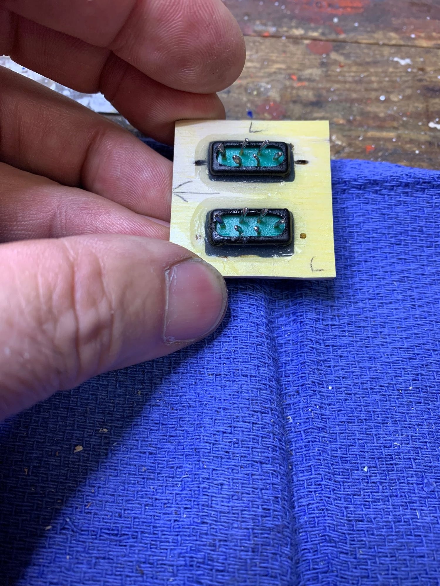
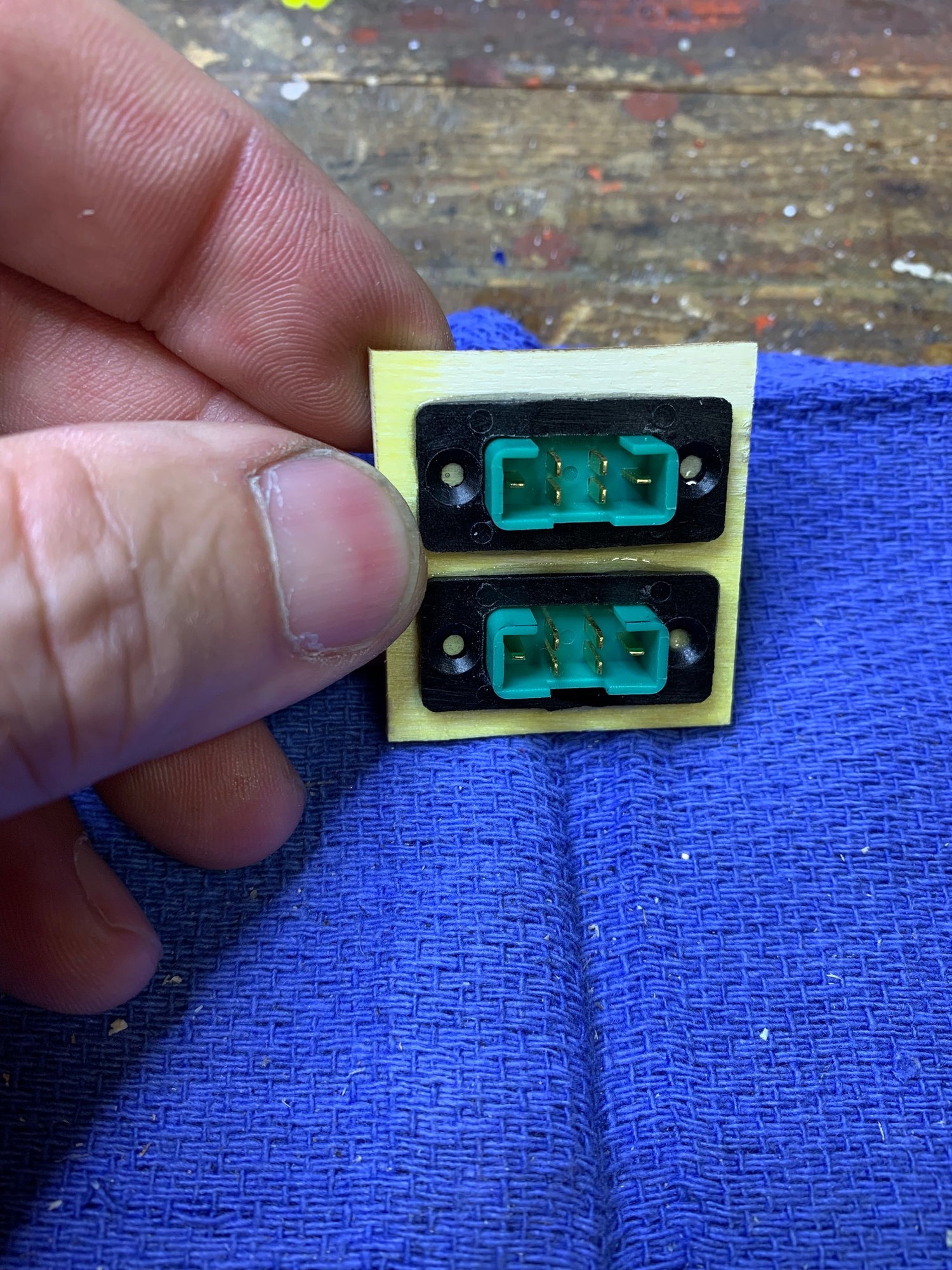
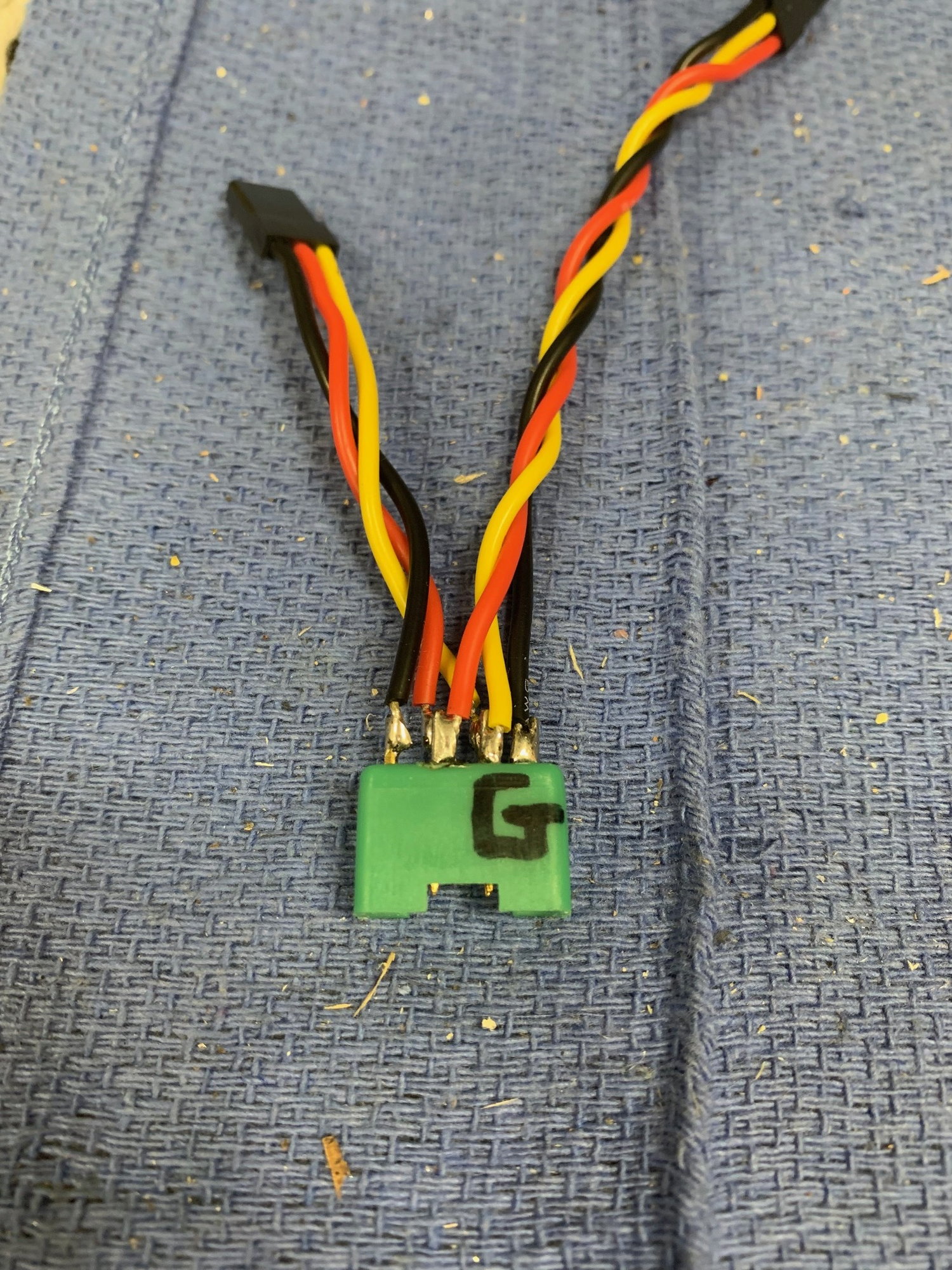
Below is a picture of my adapter that you should carry in your field bag. You can attach it to the wing while off the airplane to check servo operation. Now you have a way to connect to a servo driver easily. I suppose that you can also connect to your receiver with a servo extension wire attached to the adapter. The adapter also serves as a jig for both the female and male end of the connectors. Just match things up. You can see the "A" here, the other side has an "F" for flap. I always know what servo I am testing. Also, you have a way in the shop to move and test flight surfaces.
On the F-16 the connections are critical for the wing tip light LEDs. You should not connect the positive and negative to match up to this adapter. If you accidentally plug in a servo driver and the LED gets voltage without current limitation you will burn it out. LED lights need a controller to limit current. The way to prevent accidental burning out of LEDs is to wire differently. I connect the negative LED wire to where the positive wire is located on my adapter. I connect the positive LED wire to the signal wire location on my adapter. If I attach my servo driver through the adapter to the MPX connector that runs the LEDs there is no way voltage or current will flow to the LED.
The same must be done to the positive and negative of the electrified landing gear motor. I have a separate adapter made for the operation of the gear. It is the way you move gear in and out on the bench or at the field after you take the wing off the plane. I hook up my adapter to the Down and Locked remote gear controller. The negative is as my regular flap/aileron adapter but the positive goes to the signal wire location. The controller reverses the voltage on these positive and negative leads to move the gear in and out. Again, if you accidentally hook this particular adapter to the LED MPX nothing will happen. On the back side of my "Gear" controller adapter is the normal servo connection as in my flap/aileron adapter. It is to run the gear door servo by connecting to a servo driver.
I have no adapter to run the LEDs. 'Just have not needed to do this yet.
Note that it looks as though several wires are attached to the same MPX peg. It just looks this way. All 6 wires are to separate pegs on the MPX connector.
Note: I do not use any grease of any type on the MPX connections to make them slide easier. The smallest amount of grease that may accidentally get on a wire connection could be fatal.
Also, you must have excellent soldering skills.
AEHaas
Last edited by aehaas; 01-24-2019 at 08:28 AM.
01-25-2019, 04:46 PM
#85
Thread Starter
Tomorrow I will throw things together for an early CG estimation. I am ready to place some battery pockets up front. There is still a lot of work.
'Should be interesting...
'Should be interesting...
01-26-2019, 08:10 AM
#86
Thread Starter
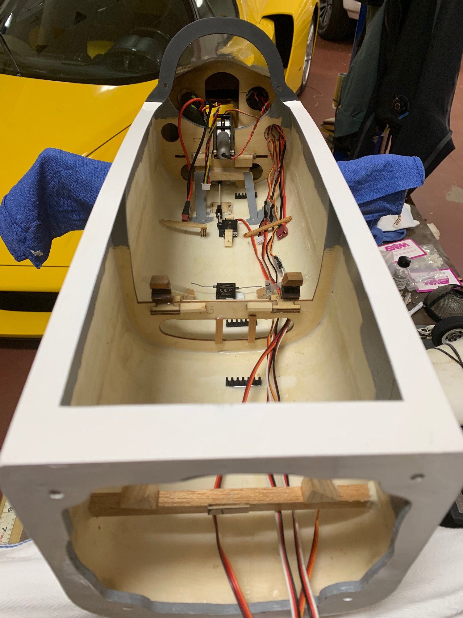
I have everything on/in the model. There is 5oz for each pilot as well. Not included is a fuel fill of the UAT that is in front of the fuel cells. Nor the cables that will go from the batteries back to my receiver that is in the engine compartment. Everything will be accessed from the engine compartment. There will be no need to open the canopy hatch at the field. My batteries are taped to the tip of the nose as you can see. I am balanced to 110mm right now. I usually balance with about 10 percent of the main fuel cell filled as well. Clearly I will be a little nose heavy when all these things are added so I will be moving batteries back some. I have not done a total weight yet.
I will not need to be adding any nose weight.
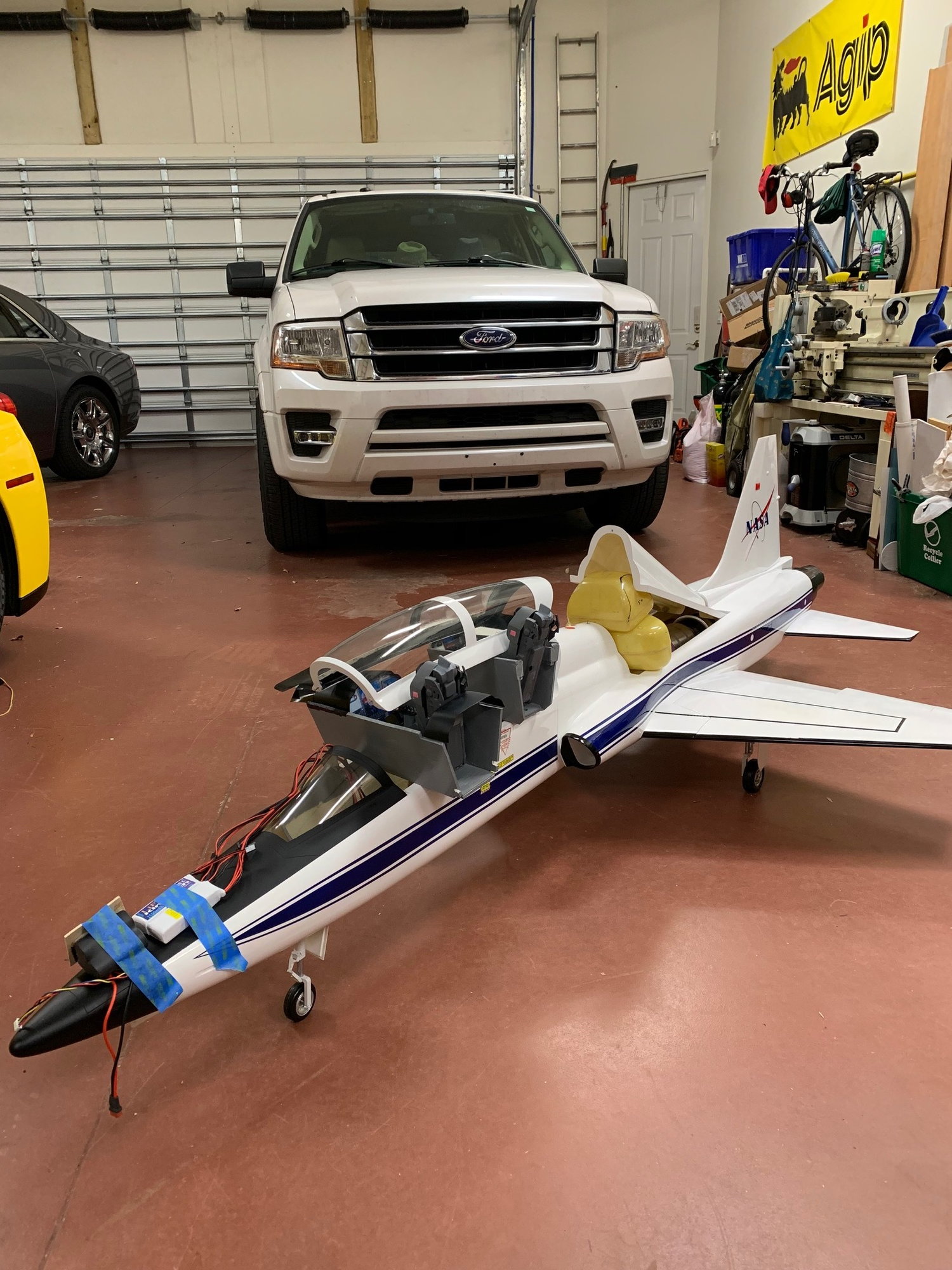
I will not need to be adding any nose weight.


 01-26-2019, 11:52 AM
#91
Thread Starter
We are downsizing the house in a few years and have been starting to sell our sports cars but the Enzo will be the last one to go, just too much eye candy to give up. Do you know this man who is standing with my wife next to her Lamborghini?

Anyway, we should stay on topic so PM me if you have to have more pictures.
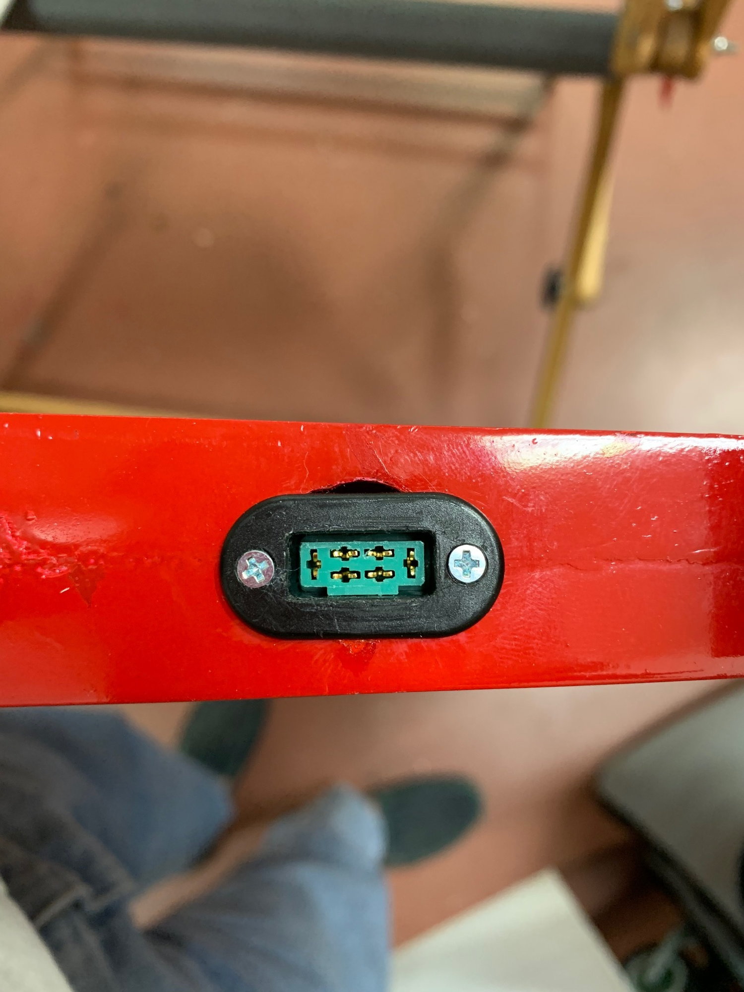
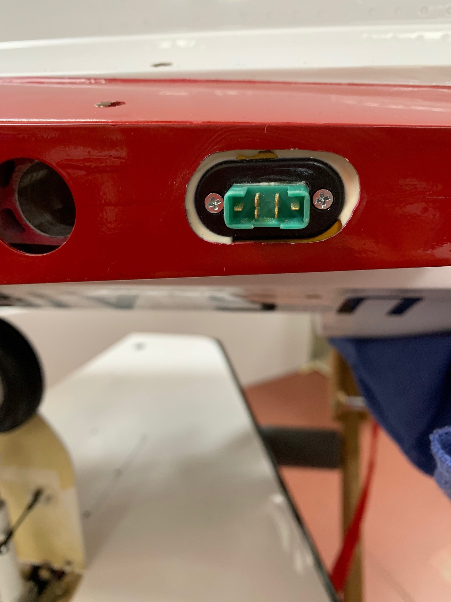
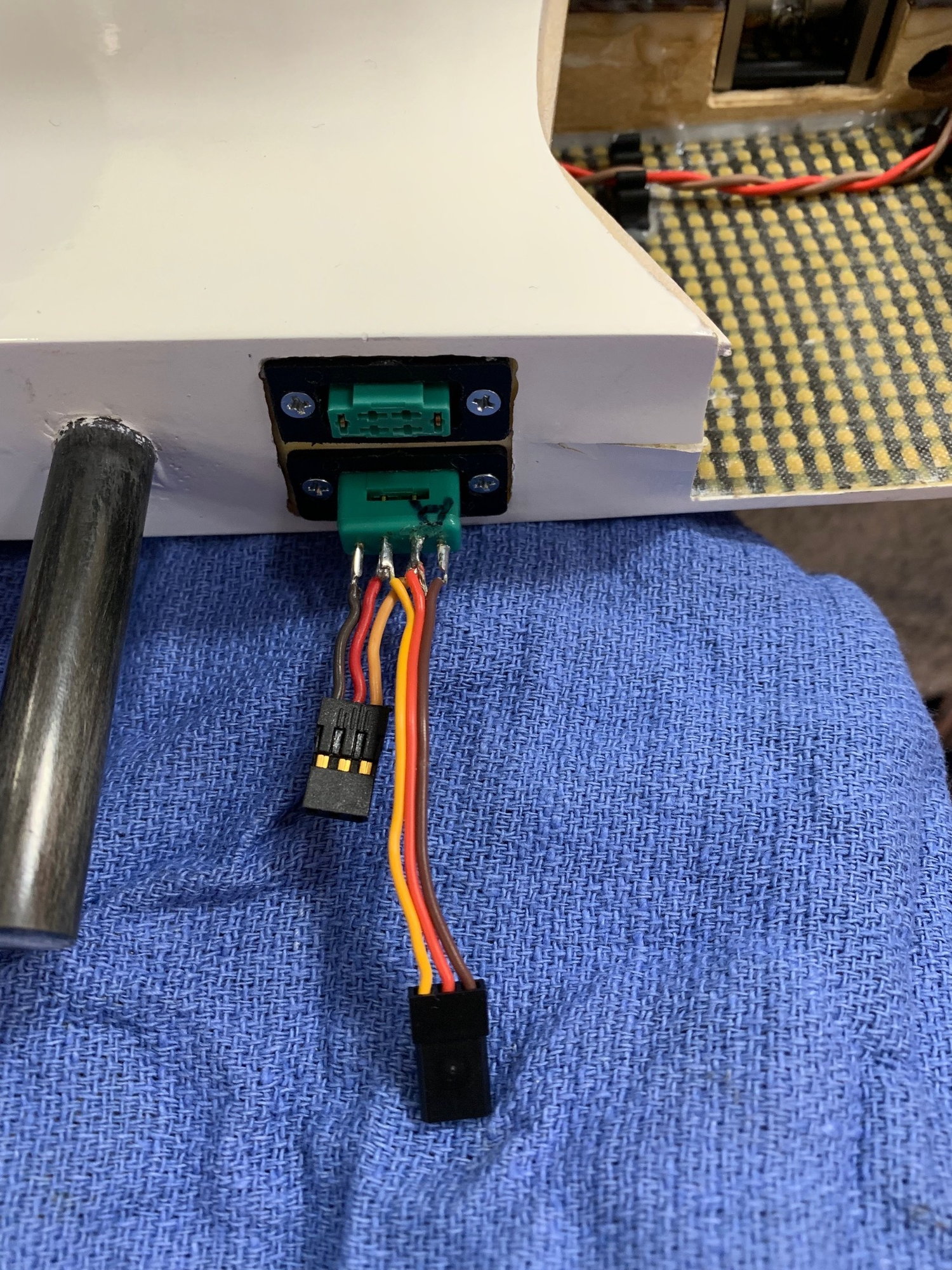
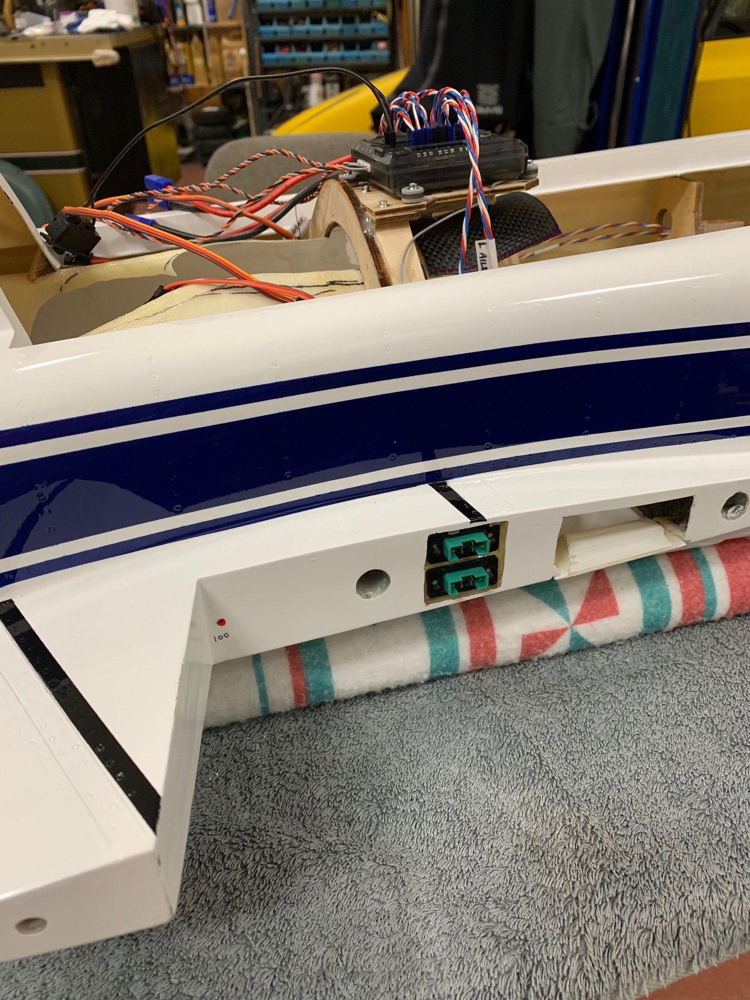
Here is a picture of the finished fuselage side of the MPX connectors. The leads are connected to the receiver above.
AEHaas
Anyway, we should stay on topic so PM me if you have to have more pictures.
Here is a picture of the finished fuselage side of the MPX connectors. The leads are connected to the receiver above.
AEHaas
Last edited by aehaas; 01-26-2019 at 11:59 AM.
01-27-2019, 05:44 AM
#93
Thread Starter
More progress:
I always put small screws to mark the CG in case there is a question at the field. You can reach underneath and feel the spot to hold the plane up. Also, when I do the CG with the Xicoy rig I can instantly compare to the “hold it up with your fingers” method. One method verifies the other.
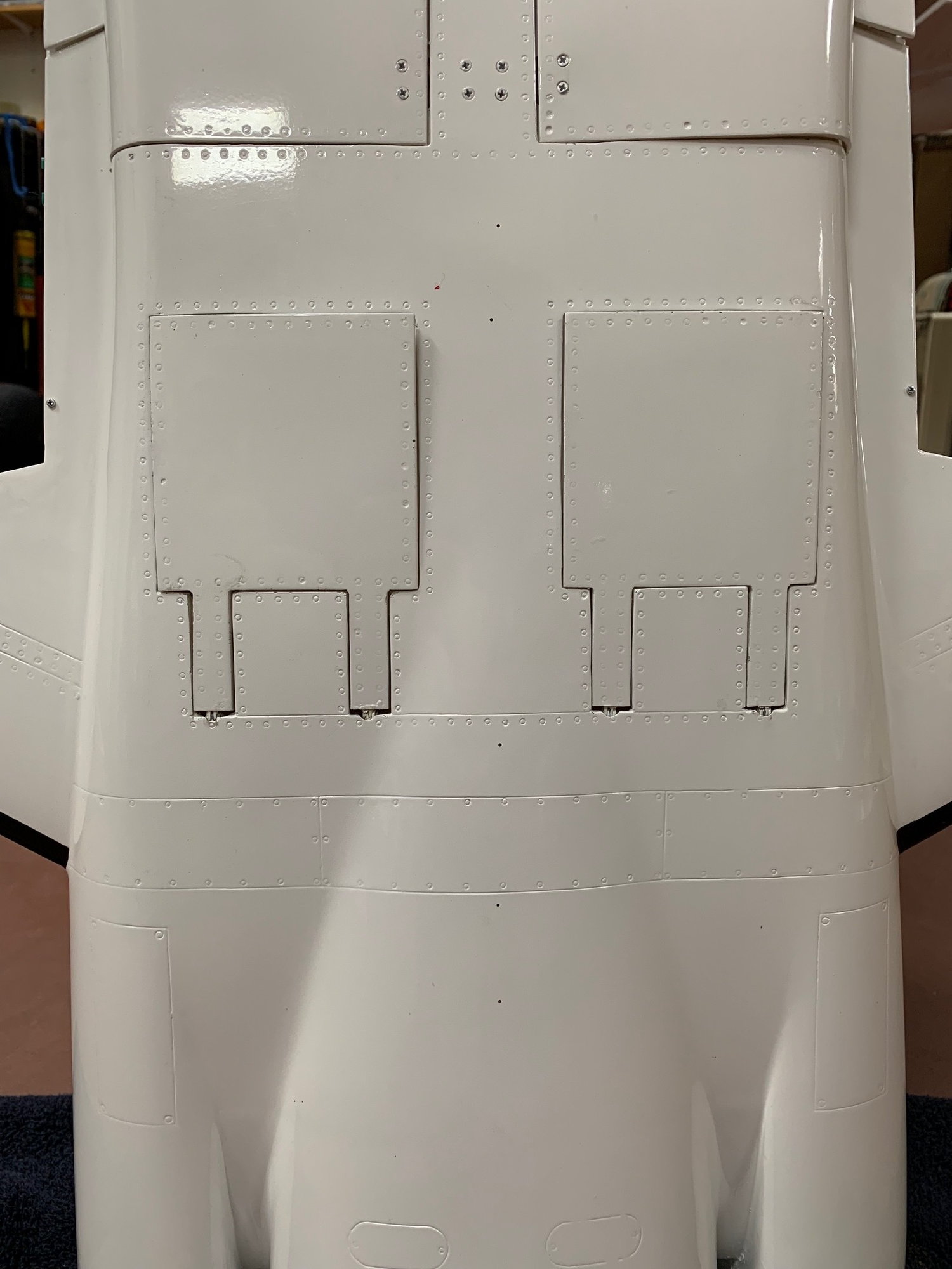
You can also see minute holes in many places in the central bottom of the fuselage. I use #60 drill holes in "low" spots so any fuel spilled can easily drain out.
Here is the battery pocket for the 2100 mA 2 cell flat LiFe battery in the nose next to where the nose gear retracts. I also have a glued in tray in the nose tip with a piece of Velcro in case I need to put the 3 cell LiFe up there.
Right now the 2500 mA 3 cell ECU A123 LiFe is next to the nose gear retract mechanism. This battery will also power the Down and Locked gear controller. The remaining 2 cell flat LiFe receiver battery can be placed opposite the one up front at the nose or moved to any location further back as needed for the final balancing. Of course there may be changes after the first few flights. I still need to make extensions for the batteries back to the ECU and receiver. I have connections up front for all the lines. If I need to remove the front of the fuselage (required for example to remove and service the main fuel cell) it will not require disconnecting lines from the area of the receiver.
You may ask how I charge the batteries. As the batteries are LiFe rather than LiPo they are intrinsically safe. They can be left in place while charging. I charge only from the balancing line at a 2 amp rate. The JST connectors are rated for 3 amps. I made an adapter that allows for charging and still balancing with just the JST connection at the battery. The other end has the balance plug and the separate positive and negative plugs.
In general I like the balanced airplane to require a small amount of pushing the elevator while inverted. That way I can go inverted, make a turn, then slowly fly down for a low pass of the runway:
AEHaas
Yes, it is Valentino Balboni of Lamborghini. We were at an event. Linda pulled up and whipped the Murcielago back into a tight parking spot in one fell swoop. Out steps a tall blond in heels. Valentine saw this and instantly became Linda's friend.
I always put small screws to mark the CG in case there is a question at the field. You can reach underneath and feel the spot to hold the plane up. Also, when I do the CG with the Xicoy rig I can instantly compare to the “hold it up with your fingers” method. One method verifies the other.
You can also see minute holes in many places in the central bottom of the fuselage. I use #60 drill holes in "low" spots so any fuel spilled can easily drain out.
Here is the battery pocket for the 2100 mA 2 cell flat LiFe battery in the nose next to where the nose gear retracts. I also have a glued in tray in the nose tip with a piece of Velcro in case I need to put the 3 cell LiFe up there.
Right now the 2500 mA 3 cell ECU A123 LiFe is next to the nose gear retract mechanism. This battery will also power the Down and Locked gear controller. The remaining 2 cell flat LiFe receiver battery can be placed opposite the one up front at the nose or moved to any location further back as needed for the final balancing. Of course there may be changes after the first few flights. I still need to make extensions for the batteries back to the ECU and receiver. I have connections up front for all the lines. If I need to remove the front of the fuselage (required for example to remove and service the main fuel cell) it will not require disconnecting lines from the area of the receiver.
You may ask how I charge the batteries. As the batteries are LiFe rather than LiPo they are intrinsically safe. They can be left in place while charging. I charge only from the balancing line at a 2 amp rate. The JST connectors are rated for 3 amps. I made an adapter that allows for charging and still balancing with just the JST connection at the battery. The other end has the balance plug and the separate positive and negative plugs.
In general I like the balanced airplane to require a small amount of pushing the elevator while inverted. That way I can go inverted, make a turn, then slowly fly down for a low pass of the runway:
AEHaas
Yes, it is Valentino Balboni of Lamborghini. We were at an event. Linda pulled up and whipped the Murcielago back into a tight parking spot in one fell swoop. Out steps a tall blond in heels. Valentine saw this and instantly became Linda's friend.
Last edited by aehaas; 01-27-2019 at 08:49 AM.
01-27-2019, 03:07 PM
#94
My Feedback: (20)
Great idea on drilling weep holes for fuel drainage. I do it also. I've only had two kinds of RC jets, those that will spill and those that will spill again. The holes get rid of it before it can be a real problem inside. Great photos.
Gary
Gary
01-27-2019, 05:09 PM
#95
Thread Starter
Another Haas modification:
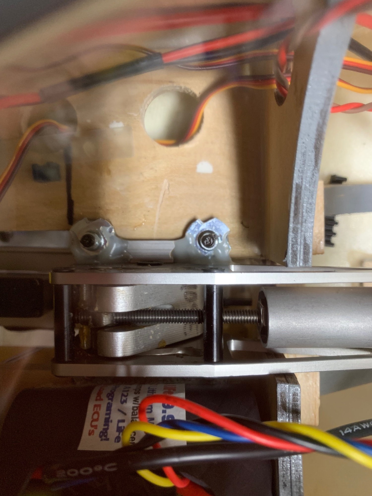
The stance of the plane was good and level when I got the CG very close to 110mm. I find however that the main gear will always take most of the weight, especially when fueled up. This gives planes an unaccounted for nose up aspect that I do not like. So I mounted the nose gear assembly on top of the plywood mount instead of the recommended bottom location. This gives a nose down location by 1/4 inch. Again, when I fuel up the plane will be perfectly level again.
I epoxied blind nuts to the top of the gear frame so I will not have to deal with nuts and bolts should the gear need servicing. On the bottom side I have large carbon fiber washers shaped to fit the space. If I damage the nose gear mounts on a bad landing I figured out a way to repair it by using the flex plates from my BVM Bandit nose gear mount. The main problem at our relatively short runway is an occasional short or long landing that may result in landing gear mount damage.
I have not yet figured out a way to add flex plates to the main gear in the wings. As I said earlier I try to figure out how things will most likely fail. I make modifications to help minimize damage. Then I design the build for easier repair work at the same time. If anybody has any more suggestions in this regard I would appreciate the feedback.
Last edited by aehaas; 01-27-2019 at 05:15 PM.
01-27-2019, 05:51 PM
#97
Thread Starter
If I have to change the mounting location to that of the original plans it would be easy enough. Your point is well taken and I will look out for this on the first few flights.
Of course there is the fact that the fuel normally sits well in front of the CG on this plane so take off may be hindered by this excessive nose weight. Also, the greater the fuel capacity the greater the problem. I have a modest 3.5 liter supply and it is nearly centered over the CG. This has to minimize the problem you are describing on the stock build I would think.
AEHaas
 01-29-2019, 06:27 PM
#100
Thread Starter
I spent over an hour today with Mitch at Down and Locked. I was having trouble programming my gear and doors that are all electric. Of course I wanted it My Way. The usual workings were not for me.
I was easily able to get the gear up and down. But the doors were an issue. Also I wanted the gear to move faster than the usual 10 seconds that electric struts are made to move. Pneumatic gear generally slams up and down. Electric movements are generally too slow. I wanted the gear doors to move open and close slowly, not the instantaneous speed of pneumatic doors. I thought 1.5 seconds was realistic, maybe 2 seconds. I will see how it looks when I get it all working. This can all be achieved.
But there are issues. For example the main gear struts drop the wheels from the inside center of the fuselage. But the gear doors are hinged centrally meaning they must be fully open before the gear struts can begin to move the wheels down. There needs to be a delay deploying the gear to begin opening. This can be done. The doors must close after the gear is down as well. This was easy to do, just a check box to program.
There are safety features. For example, if the gear does not fully retract the controller knows this and prevents the gear doors from closing. The gear controller is very smart but needs programming to do it right and very specific as in my case. I am happy to have such realistic gear operation. I will continue the programming tomorrow and finish it up.
Next comes the �routine� programming of the surfaces and my mixes. I have a lot planned. For example, in my BVM Bandit I programmed the spektrum AS3000 gyro to double the strength of the gyro settings when both the gear is down and the flaps are set for landing. Somebody mentioned they needed a gyro on the nose wheel. The AS3000 can do this. I always use a little crow on both take off and a little more on landing flaps. I will program the air spoilers/brakes to deploy half way with the wheel brakes (proportional) set at half strength and fully deploy the air brakes with the wheel brakes on full.
I am waiting for Jet-Tech to make my custom 1 liter header tank that will be centered over the CG. Once I get that I will be ready for the final CG balance and turbine test run. I am getting close.
AEHaas