


New TopRC T-28 Trojan


 05-19-2024, 01:28 PM
#304
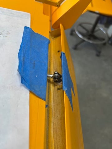
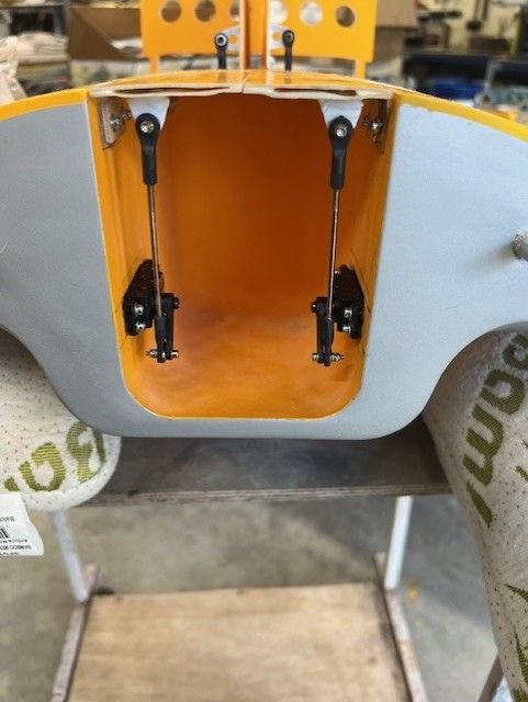
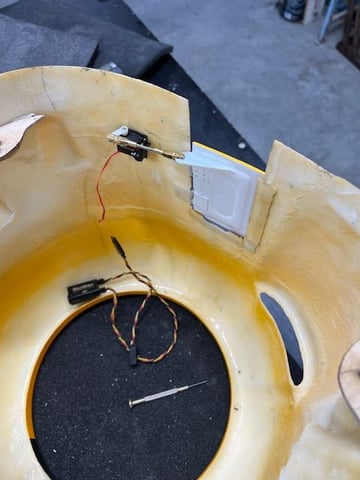
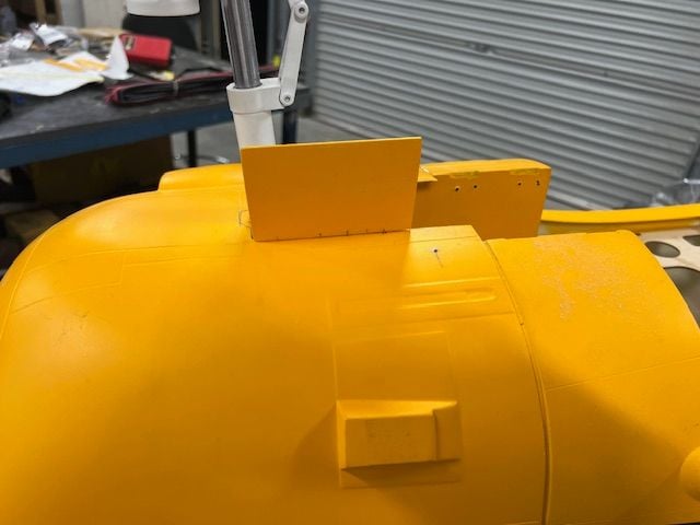
Linkage for ailerons are in, just need to connect to servo arm and adjust.
I made test rig to see where the best place for the linkage on leading edge would be, middle seems to be the sweet spot.
I made test rig to see where the best place for the linkage on leading edge would be, middle seems to be the sweet spot.
05-20-2024, 12:43 PM
#305
Having issues with geometry for ailerons with the internal linkages, a number of factors at play and remediations steps I will take.
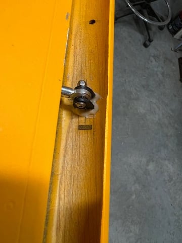
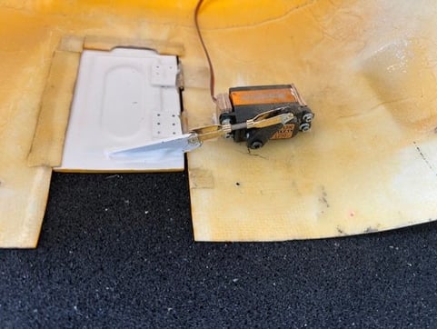
1. I put the the location of control horns in the middle of leading edge, they should be hard up against the bottom aileron skin as you can get it, i.e furthest from the hinge pivot. I'm getting another set of horns and will grind the existing ones down with the dremel.
See photo, the horns need to go hard against the very right hand side skin in the photo.
2. I made the hole in control horns slightly too large, not by much but it does allow a small amount of slop. I will drill and tap M3 with the next set of horns so there is no slop.
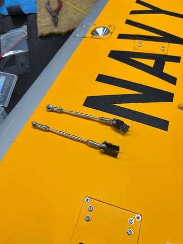
3. Servo arm is far too long and and the small amount of gear train and other slop movement is amplified by this length, I will experiment with locations till I only have enough travel for the flaps and will drill / tap a new M3 hole to suit in the alloy arm.
4. Lastly and thanks to Jason for pointing this out the servo hatch is far too flexible for the loads it will experience, I am going to laminate 2 layers of heavy weight carbon cloth to the bottom which will stiffen it up immensely, I will also add a second pair of mounting holes on the long sides. (will also do this to the flap hatch)
5. I may also consider adding a strip of 1/8th balsa sheet along the inside of the wing skin trailing edge just before the hinge point in case there is a bit of flexing there. Undecided on that yet.
This is my first crack at a very large model with very scale control surfaces so has been a learning curve.
Grateful I received very sage and experienced advice from a few people, Ross & Jason who is on this thread.
I got told yesterday there are a couple of these with I assume similar setup for ailerons and they experienced severe aileron flutter, one at Joe Nall during maiden flight, it only did 1 circuit but got down ok.
Failing all the above working I will install external G10 horns and linkage that way.
Live and learn.
1. I put the the location of control horns in the middle of leading edge, they should be hard up against the bottom aileron skin as you can get it, i.e furthest from the hinge pivot. I'm getting another set of horns and will grind the existing ones down with the dremel.
See photo, the horns need to go hard against the very right hand side skin in the photo.
2. I made the hole in control horns slightly too large, not by much but it does allow a small amount of slop. I will drill and tap M3 with the next set of horns so there is no slop.
3. Servo arm is far too long and and the small amount of gear train and other slop movement is amplified by this length, I will experiment with locations till I only have enough travel for the flaps and will drill / tap a new M3 hole to suit in the alloy arm.
4. Lastly and thanks to Jason for pointing this out the servo hatch is far too flexible for the loads it will experience, I am going to laminate 2 layers of heavy weight carbon cloth to the bottom which will stiffen it up immensely, I will also add a second pair of mounting holes on the long sides. (will also do this to the flap hatch)
5. I may also consider adding a strip of 1/8th balsa sheet along the inside of the wing skin trailing edge just before the hinge point in case there is a bit of flexing there. Undecided on that yet.
This is my first crack at a very large model with very scale control surfaces so has been a learning curve.
Grateful I received very sage and experienced advice from a few people, Ross & Jason who is on this thread.
I got told yesterday there are a couple of these with I assume similar setup for ailerons and they experienced severe aileron flutter, one at Joe Nall during maiden flight, it only did 1 circuit but got down ok.
Failing all the above working I will install external G10 horns and linkage that way.
Live and learn.
The following users liked this post:
misu77 (05-21-2024)
05-21-2024, 04:39 AM
#306
So, are you going with external control horns, for ailerons � and possibly flaps �. Or, are you just moving ail control horn close test to skin ( far right in your pic) � to prevent flutter
thanks
mark
thanks
mark
05-21-2024, 12:38 PM
#307
Flaps are done though I will reinforce the hatch and will shorten the attachment point on the servo arm.
I am working through the options outlined previously for internal linkage. New control horns are being fabricated and I will get a set of external horns as a fall back option.
I am working through the options outlined previously for internal linkage. New control horns are being fabricated and I will get a set of external horns as a fall back option.
The following users liked this post:
misu77 (05-21-2024)
05-25-2024, 02:02 PM
#308
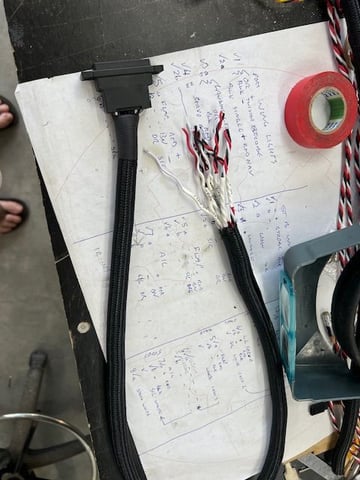
As I need to get more control horns made I have started on wing cabling and doing the 16 pin connectors. Very time consuming but could be the round MIL spec types I trained on back in late 80s.
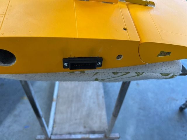
The female plug receptacle will be screwed to the face of the centre section and I will open up a slot in the outer wing face to accept that without binding.
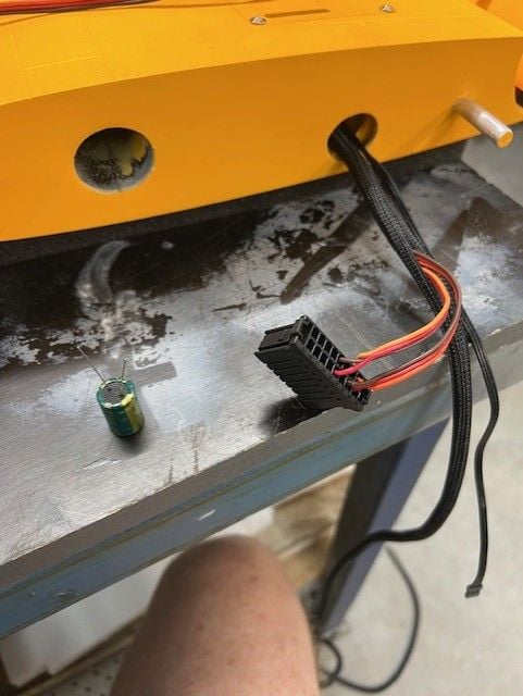
The female plug receptacle will be screwed to the face of the centre section and I will open up a slot in the outer wing face to accept that without binding.
05-26-2024, 02:46 PM
#309
Spent most of yesterday doing wiring on outer panels, they are pretty much done apart from securing the loom within the wing.
Have started on the centre section, there is a lot going on in there with wiring and taking my time working through it.
There will be 3 main looms that come out, each with a 16 pin connector and these will feed up inside the fuz.
There will also be the battery lead for the retracts controller as that will be located inside the speed brake bay.
Using a JR HV multi box to drive the 3 nose door servos and it is fed from the retract controller, allows fine tuning of end points separately.
Wish I had more of the HV version.
The nose doors are split so centre section can be removed. There is a nylon torque tongue that joins them.
Not sure on location for switches yet, I have the powerbox main switch and 3 other accessory switches to place.
I was thinking access them via the open speed brake but have them fitted to the fuz wall or . . .
Access within the fuz by removing canopy and cockpit tub.
05-27-2024, 03:04 PM
#310
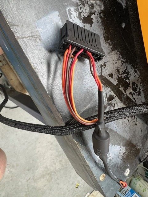
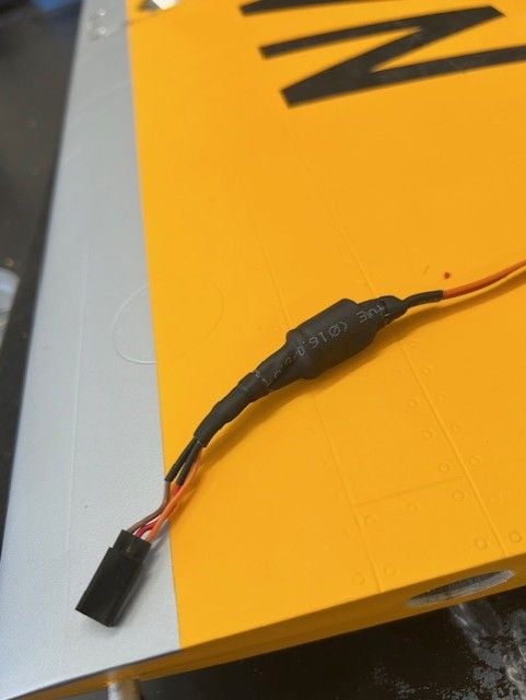
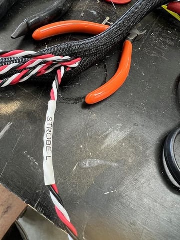
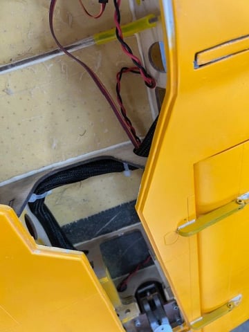
more wiring. First loom is in the wing. I had to remove the flexible cover as the leg was pushing on it and not closing properly, have laid the cables flat against wing skin and secured in place.
Photos showing the new label maker, very happy with it and it is a piece of piss to use.
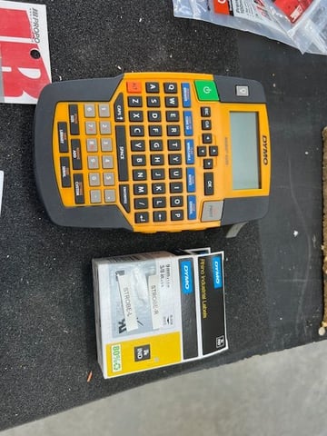
Photos showing the new label maker, very happy with it and it is a piece of piss to use.
06-02-2024, 12:44 PM
#311
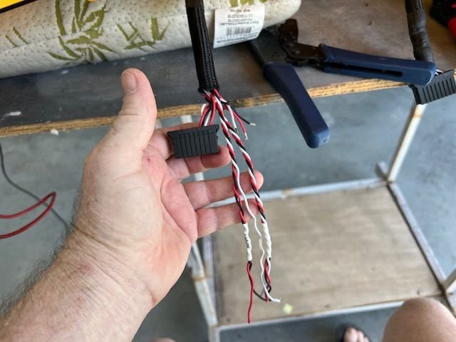
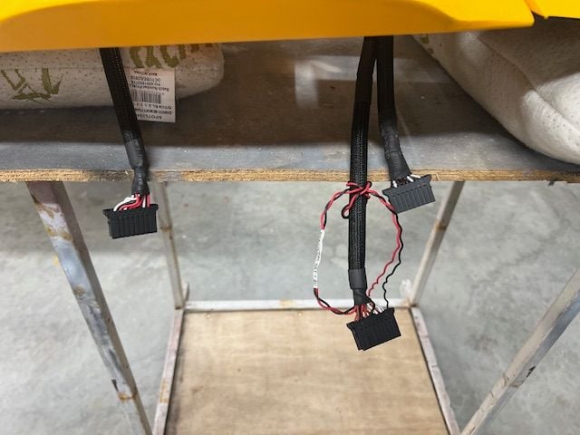
Wing wiring looms are done. There are 3, one each for outer panels and one that is the aux functions within centre wing, nose retract, nose door, brakes, retract signal etc.
Still need to tidy up a few things with cable ties but need to complete final programming of the JR Multi-box to nose gear door first.
The loose wires on one loom are for the controller battery input.
The TopRC retract controller has also been fitted with double sided tape.
Next job will be to fit servo for that little nose gear door and set its throws.
06-04-2024, 04:11 PM
#312
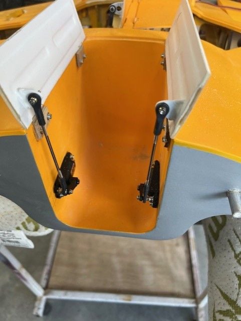
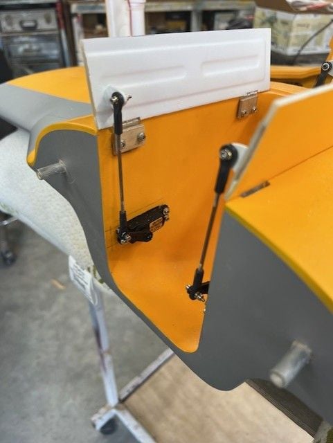
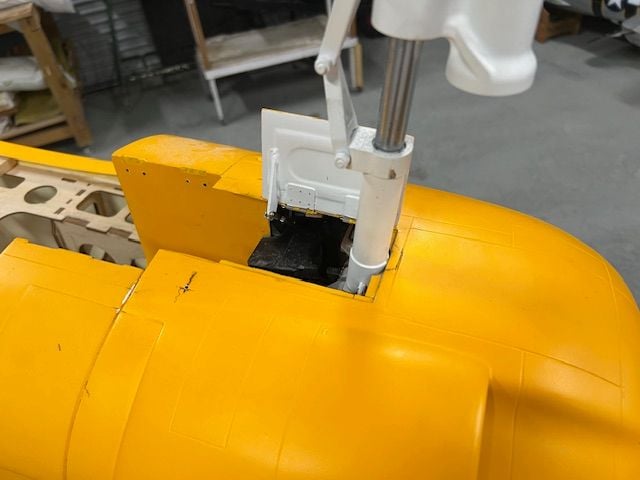
made a start on the front gear door mechanism, the concept works ok though a servo with a little more torque would be good. This micro digital servo is 3.8kg but is super small in size which I need as there is very limited room.
I do have savox mini servo which is about 10kg however I think it will be too large.
I'll play some more with it and see. I do need to flip it over so that the shaft is towards the front and move the servo closer to the opening. I would like the door to open a bit more than it does however the way I did the hinging prevents it, it goes over centre about 15 degrees which is ample.
06-05-2024, 08:11 PM
#313
Have changed the nose door servo to a Savox 1250 mini which is 8kg @7.4v, yes it's overkill but it is working a lot better than the tiny micro Dual sky servo.
Will be starting on the fuz fitout next. Still waiting on new aileron control horns to be sorted, no rush as I have others things to get on with.
Will be starting on the fuz fitout next. Still waiting on new aileron control horns to be sorted, no rush as I have others things to get on with.
06-09-2024, 12:21 PM
#314
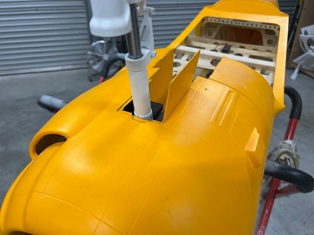
ok change of plan with nose gear servo, had to go back to the Dualsky DS169 micro servo as the nose leg steering mount was fouling on the larger mini sized servo.
All is in and working fine, did multiple cycles, adjusted linkages on the long doors a little.
Now onto the fuz fit out.
All is in and working fine, did multiple cycles, adjusted linkages on the long doors a little.
Now onto the fuz fit out.
The following users liked this post:
misu77 (06-09-2024)


